Hello Hofmann and Hello MS,
Do buy a multimeter and check it for yourselves, it's very simple as are the calculations. The audio caper is full of snake oil and someone says something erroneous someone else repeats it and before long it's gospel 🙂
Cheers
I agree about the board it's as good as you'll get.
Do buy a multimeter and check it for yourselves, it's very simple as are the calculations. The audio caper is full of snake oil and someone says something erroneous someone else repeats it and before long it's gospel 🙂
Cheers
I agree about the board it's as good as you'll get.
For stereo application, for sound quality, which would be your choice:
1. HIFI??2.0??? TPA3116D2????????? DC10-25V-???
or
2. TPA3116 2.0 ??? WIMA???????( 100W+100W)-???
or
3. KYYSLB DC12 24V High Power 100W*2 TPA3116D2 Digital Power Amplifier Board XH M590 Home Audio Amplifier Board 2~8 Ohms|Amplifier| - AliExpress
Cheers
1. HIFI??2.0??? TPA3116D2????????? DC10-25V-???
or
2. TPA3116 2.0 ??? WIMA???????( 100W+100W)-???
or
3. KYYSLB DC12 24V High Power 100W*2 TPA3116D2 Digital Power Amplifier Board XH M590 Home Audio Amplifier Board 2~8 Ohms|Amplifier| - AliExpress
Cheers
Hi people, I’ve modified a few tpa3116 amps, but now I’m looking at building my own. It’s going to be 2.2 4x100w using 2 of the KYYSLB XH-A261 boards and a minidsp 2x4 board to handle the crossovers. 2 questions, I’d like to use a stepped attenuator to control volume, is it just a case of wiring these inline with the input of the amps, also what resistance value would I be best off with. And what kinda power supply would I be looking at? 10A 24V? Thanks in advance.
Last edited:
I think first of all look at amps that don't have an opamp preamp as they usually are badly implemented and use shoddy quality opamps. With today's sources it's usually not needed. If your source is good you can even turn down the tpa3116 gain, reducing the overall noise.
Then you need to know your speaker impedance and adjust the output capacitors for a flat response. Make sure the output inductors are 10uH not 33uH. Also would be great if input caps would be polypropylene type if possible.
Power wise you should cover the max volume you are willing to listen to for any amount of time.
Next best audio quality gains would be looking into converting to balanced, remove the passive crossover in your speakers and add an active crossover along with biamping (or triamping depending on speaker). For a good channel separation use mono boards for each speaker (in case of tri-amping you need 6 mono boards). But this is not so beginner friendly.
For stereo application, for sound quality, which would be your choice:
1. HIFI??2.0??? TPA3116D2????????? DC10-25V-???
or
2. TPA3116 2.0 ??? WIMA???????( 100W+100W)-???
or
3. KYYSLB DC12 24V High Power 100W*2 TPA3116D2 Digital Power Amplifier Board XH M590 Home Audio Amplifier Board 2~8 Ohms|Amplifier| - AliExpress
Cheers
I have the 1st and the 3rd you show. The 2nd you show should perform very close to the 3rd but has the disadvantage of glued heatsinks.
I prefer the 3rd over the 1st, among other because of the use of foil capacitors at the input and output. Mine is playing great.
Thankyou FauxFrench for your reply.
The 3rd one I will get a pair then to power a pair of Lx-mini.
(LXmini construction)
And I will be using a VT-25A DHT pre amp with it.
What DC voltage are you using ?
Would you do any modifications to it ?
Cheers.
The 3rd one I will get a pair then to power a pair of Lx-mini.
(LXmini construction)
And I will be using a VT-25A DHT pre amp with it.
What DC voltage are you using ?
Would you do any modifications to it ?
Cheers.
It can take 24V but I use a 19.5V 96W laptop supply. I have more than enough power.
My modifications are described in posting #11517 of this thread. This is why it is important that the heatsink can be removed easily when you modify the gain. Read also jemraids very good report in posting #11537.
As "value for money", it is the best one I know.
Good luck with the project.
My modifications are described in posting #11517 of this thread. This is why it is important that the heatsink can be removed easily when you modify the gain. Read also jemraids very good report in posting #11537.
As "value for money", it is the best one I know.
Good luck with the project.
Faux French
Just get back from the supplier of the 3rd one, the output chock is rated at 33 uH and 5A/
Does this agree with the info you have ?
We may need to change those chocks, may be ??
Just get back from the supplier of the 3rd one, the output chock is rated at 33 uH and 5A/
Does this agree with the info you have ?
We may need to change those chocks, may be ??
Trileru has done a very good analysis job in the posting he refers to.
I looked at the question in a more simple way. I removed my XH-M590 from the speakers/power supply and tried to measure the choke value "in-circuit" but my meter refused to display a value, both measuring on a single choke and with two chokes connected in series (still in-circuit). My chokes have been stabilized mechanically with thermal glue so removing one would be a more extensive job.
The chokes have only few turns so my impression was a 10uH value. You were told 33uH/5A.
The output filter capacitors are 680nF. NXP suggests 680uH/22uH with 8 Ohm loads. 680nF/22uH gives a cut-off frequency of 41KHz. Is the choke 33uH instead of 22uH, the cut-off frequency is lowered to 34KHz. Still acceptable with a very slight drop at the highest frequencies. At least I cannot hear 20KHz. I would only worry about that slight drop if you are convinced that you can hear the difference.
The reason why 33uH is often disapproved for TPA3116 is that the chokes used with TPA3116 are often of the type shown in your first amplifier. Such chokes can handle in the order of 5A (peak) with a 10uH value but only in the order of 3A (peak) with a 33uH value. 3A peak means 18W in 4 Ohm, 27W in 6 Ohm and 36W in 8 Ohm. For 4 and 6 Ohm speakers, core saturation may appear and it will hardly sound good. But, the 33uH toroidal chokes initially mounted are told to saturate above 5A (peak). 5A (peak) means 50W in 4 Ohm, 75W in 6 Ohm and 100W in 8 Ohm. For 6 and 8 Ohm speakers, the supply voltage limit will prevent you from reaching such power levels. But for 4 Ohm, a 24V supply voltage can give around 70W at the output. 5A is a bit marginal. But, if you use a 20V supply instead, the supply voltage will limit the output power to 50W and the 5A is just sufficient. Thus, with 6 or 8 Ohm speakers you can use 24V supply, with 4 Ohm speakers you should limit the supply voltage to 20V (if the chokes are really 33uH/5A).
If you change the 4 chokes to 10uH/7A of a decent quality, you will have to pay the price of the whole board again (or more). For me, the initial toroidal chokes work fine with my 8 Ohm and 6 Ohm speakers. I see no need to change. Only if you are convinced that you can hear the slight high-end drop or you are really going to use 4 Ohm/70W (24V supply), you may consider changing the chokes. That's my advice.
Trileru is undoubtedly right in theory.
Last edited:
NXP? Isn't tpa3116 made by TI?
I think the datasheet states only the 10uH value. At 33uH you're loosing highs with anything 4-8ohms.
I wouldn't worry about the current rating. 3A/5A should be same thing in practice. The current rating means that they can sustain that current going through them without failing from heat. I am pretty sure no one here can stand around for much time at 3A through the coils. For 8ohm speaker that's 72W. The tpa3116 mono boards seem to be pushing 50W into 4ohms (PBTL) and that's around 3.5A. The coil resistance is dropping some voltage across it but at normal listening levels it really shouldn't matter. And for peaks/transients again, the coils should be fine. If you're going to power a subwoofer with the amp, and will rock it to the max output of the amp for longer periods of time, then maybe you should look for the 5A rated coils.
With a 8 ohm speaker and 33uH coil + 680nF cap the response starts dropping at 10KHz, well in the audible range. I'd use a maximum of 15uH on this chip regardless of the speaker impedance. Going higher will surely affect the frequency response and you can't compensate with adjusting the output capacitor value. You need to consider the speaker impedance in the output filter's response.
Also, a more accurate way of testing the output power is just using a sinewave generator app from your phone or computer, measure with multimeter on AC right at the speaker terminals. Then also knowing the speaker impedance you can easily calculate the output power. Say you dial the volume up to the loudest you can listen for any period of time, using music, then you stop the music, play a 50-60Hz sinewave and use the multimeter on AC. Most can do 50-60Hz AC for wall socket measurements, so they will be accurate enough with the shown voltage. That is the maximum power that the amp will ever output, and that you can barely stand listening. Anything above that, power supply wise, or current rating wise (for output inductors current rating), is basically useless in practical terms, as you're never going to ever realistically use it past that point.
Last edited:
I almost fully agree with you.
TPA3116 is indeed TI but NXP is giving guidelines for what L/C/Rload-combination they find best. Applicable to other class D chips without post filter feedback. TI only shows 10uH for the TPA3116 as far as I recall.
The 33uH/5A I find is a characteristic other than heat sustainable current. More current could be accommodated by thicker wire such that the resistive losses remain the same. The 5A I know is an indication of the current at which the core permeability has dropped a certain percentage due to beginning saturation. Depending on the core material, saturation can appear very fast above this current value. When the core saturates, the inductance of the choke drops radically. The drop in inductance increases not only the audio signal current but also the carrier current. Then, current limiting may be invoked and it starts sounding really bad. My understanding is that this current value relates to an instantaneous effect (saturation) that may cause signal distortion instantaneously, not an effect that relies on a time constant.
At 10KHz, 33uH should have an impedance corresponding to 2.1 Ohm. At 20KHz, 4.3 Ohm. You are right, a drop already from 10KHz but very moderate. My hearing stops around 11-12KHz.
15uH I also find is a good universal value. Yes, most people exaggerate the output power they use. Still, the output filter choke should be designed not to saturate at any possible output level.
Last edited:
Yes you need to consider the saturation current as well. Usually it's thereabouts as the RMS current rating. Depending on type/model of inductor some have the saturation rating higher than the RMS limit current.
Here are some examples:
https://ro.farnell.com/bourns/sru1063a-100y/inductor-10uh-3-8a-30-aec-q200/dp/2616957
http://www.farnell.com/datasheets/2251089.pdf
https://ro.farnell.com/epcos/b82477g4103m000/inductor-10uh-5-4a-20-full-reel/dp/2291394
https://ro.farnell.com/bourns/srr1208-100ml/choke-shielded-10uh-power/dp/1362140
https://ro.farnell.com/bourns/srr1260-100m/inductor-10uh-power-shielded-smd/dp/2212501RL
While others have the saturation current at almost half the max RMS current rating:
https://ro.farnell.com/tt-electroni...tr13/inductor-shielded-10uh-20-aec/dp/2765517
Ideally you'd get ones with known complete specs. I found some in the monkey box that seem to be having some heft to them and low DCR so I just used those. I'm not sure I usually go much past 1-5W so either way they work just fine. 10uH
Last edited:
Interesting. Sadly not many have it in the datasheet.
I was thinking that it should be defined by Isat tho I don't see they map precisely looking at Isat and the curves for this example:


Going by the Isat of the 22uH one, you'd think you'd have it all at 2.5A
I was thinking that it should be defined by Isat tho I don't see they map precisely looking at Isat and the curves for this example:
Going by the Isat of the 22uH one, you'd think you'd have it all at 2.5A
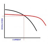
These are from Wurth selection tool. 10uH and 11-13 mm W and L.
I use the one in red. 7447709100
Ordering some this weekend.
Stay away from the yellow one. 🙂
I use the one in red. 7447709100
Ordering some this weekend.
Stay away from the yellow one. 🙂
Attachments

Last edited:
I will confirm with the supplier that the chocks are at 33 uH before I buy. If they are 33 uH, I will change them to 10 uH.
It is easier to remove the chokes if I do not need to keep it intact.
And yes, almost one choke will cost more than the board !! The board cost only US$5.7 plus shipping!!!
If they are of 33 uH, after removing them, can I change them to 10 uH by removing 1/3 of the number of turns on it, and reuse them ?
How to pick the best type of chock for the application please if I need to replace them instead ? shielded ?, SMD ?, through hole ?, like the one on the picture of the 3rd amp ?, or air core ??
Can a head phone jack be connected to the board ?
Last edited:
- Home
- Amplifiers
- Class D
- TPA3116D2 Amp