Does anyone know if the XH-M590 board has a differential input for a balanced input?
Next to the 2 RCA input sockets is a block marked from left INL - Mid Pin G?( No silk screen print) INR. If so could I assume that this can be used as a Monoblock?
Next to the 2 RCA input sockets is a block marked from left INL - Mid Pin G?( No silk screen print) INR. If so could I assume that this can be used as a Monoblock?
Last edited:
Hello P,
I have a spare X590 board, just had a look, the socket is printed INR - GND - INL
With my meter the L-R connections are linked to the same L-R's on the RCA connectors
Just another way of connecting audio but with a plug.
Cheers
I have a spare X590 board, just had a look, the socket is printed INR - GND - INL
With my meter the L-R connections are linked to the same L-R's on the RCA connectors
Just another way of connecting audio but with a plug.
Cheers
Dear Trileru,
Thank you for your effort! In last few days I made several measurements and soldered several shortcuts but could not find a final solution and I gave up the fight 🙂. I share my experience, maybe it will be useful for somebody:
In summary I could bypass the BT chip with some shortcuts, but the whole operating was not stable and the pop-up (+pop down) noise was very srong with Giancarlo anti pop up Circuit too. So I do not want to spend more time with this board I will buy another one without Bluetooth. 🙂.
gsc73
Thank you for your effort! In last few days I made several measurements and soldered several shortcuts but could not find a final solution and I gave up the fight 🙂. I share my experience, maybe it will be useful for somebody:
I found two pins on the BT chip that has an effect to the Mute pin and the pre-amplifier part (TC072) but I could not bypass this section 100%. There were no power supply for TC072s without BT crystal.😱I am 99% there's no enable from the BT chip.
I checked this assumption with frequency meter but the BT chip does not pull to the ground the outputs.Most probably the BT chip outputs are pulled to ground when the crystal is missing/chip is not working.
I removed the complicated original Mute circuit and build a simple 100K resistor to ground. It was OK.tpa3116 has pin 12 as mute pin...
In summary I could bypass the BT chip with some shortcuts, but the whole operating was not stable and the pop-up (+pop down) noise was very srong with Giancarlo anti pop up Circuit too. So I do not want to spend more time with this board I will buy another one without Bluetooth. 🙂.
gsc73
I have been modding my XH-M590. So far I have only bridged the reverse polarity diode and made a regulated 24v 5A PS.
I thought that the PS was faulty as the XH Led would light and immediately dim and the amp would not turn on. Lots of head scratching, trying it with other amps etc etc. Assumed it had to be the XH board and removed the diode bridge wire.....et voila, it was that. I have not seen that any others have had this happen?
Now I can try it properly with the existing on-board PS caps and see if they need to be upped.
Am I right to assume that the input caps are the 4 MKP type blue caps? The are marked 1u 63v. Has anyone increased these to say 2.2 or 4.7uf?
I am a bit confused as to why there are 4. I would have expected only 2. There are 2 polarised 100uf caps next to the 4 blue behind the alternative input block (white 3 pin) What are these for?
I want to use a tpa3116 board to make active speakers. I've tried multiple of the different boards, and have come to realize that it's better to use one of the modules without onboard volume control, preamp or bluetooth. Since the amp module is inside the speaker, output filters aren't strictly necessary. I've bought a couple of these filterless tpa3116d2 boards. Have not tried them yet but the signal and power traces on the pcb seem rather small for supposedly 100w.
That made me go back to the tpa3118 modules I experimented with a while back. It seems their PCB design is superior to most or any of the other commonly available chinese tpa311x boards. And sound quality is very impressive in my experience. However their are marketed as 60w instead of the tpa3116d2 as 100w.
Can anyone explain me what exactly determines the total amount of power that different configurations of this board can deliver? The impedance of the speakers of course , but what other factors are there?
DC 12V 24V 2x50W Dual Channel Mini Digital D Class 50W+50W TPA3116D2 50W Power Amplifier Board|Integrated Circuits| - AliExpress
1pcs TPA3118 PBTL mono digital amplifier board 1X60W 12V 24V POWER AMP|Integrated Circuits| - AliExpress
The output filters add distortion, and I agree, is better with a minimal filter/no filter and to keep the speaker wires short instead.
The evaluation module has basic inductors, not huge, loosely wound antennas, huge film capacitors.
The evaluation module has basic inductors, not huge, loosely wound antennas, huge film capacitors.
I want to use a tpa3116 board to make active speakers. I've tried multiple of the different boards, and have come to realize that it's better to use one of the modules without onboard volume control, preamp or bluetooth. Since the amp module is inside the speaker, output filters aren't strictly necessary. I've bought a couple of these filterless tpa3116d2 boards. Have not tried them yet but the signal and power traces on the pcb seem rather small for supposedly 100w.
That made me go back to the tpa3118 modules I experimented with a while back. It seems their PCB design is superior to most or any of the other commonly available chinese tpa311x boards. And sound quality is very impressive in my experience. However their are marketed as 60w instead of the tpa3116d2 as 100w.
Can anyone explain me what exactly determines the total amount of power that different configurations of this board can deliver? The impedance of the speakers of course , but what other factors are there?
DC 12V 24V 2x50W Dual Channel Mini Digital D Class 50W+50W TPA3116D2 50W Power Amplifier Board|Integrated Circuits| - AliExpress
1pcs TPA3118 PBTL mono digital amplifier board 1X60W 12V 24V POWER AMP|Integrated Circuits| - AliExpress
I understand your surprise that with the same chip inside, one is rated at 100W while the other only at 60W. There is, however, the difference that the TPA3116D2 has a cooling-pad on the top of the housing (for a heatsink) while for the TPA3118D2 the cooling-pad is arranged downwards and conducts heat-loss to the PCB only. I believe TI has realized that it is not possible to get rid of more than in the order of 6W to the PCB.
Short speaker wires reduce the problem with radiated noise but no output filter leaves a 24Vp square-wave signal directly on each speaker. How that will influence the performance of in particular a treble dome at audible frequencies, other members can better judge upon.
Last edited:
Many thanks for the photos. Can't make high-res photos work.
My changes:
1) The two "753" (75K) resistors are removed in order to reduce the gain (and hiss) to 20dB.
.
Hi FF, sorry for the stupid question🙂
You wrote:
"The two "753" (75K) resistors are removed in order to reduce the gain (and hiss) to 20dB."
I just need to remove the resistors or do i need to remove them & bridge the connector?
Can i remove the Potentiometer? If yes, what do i need to do for that?
Thanks in advance
Udi
Just remove the two 75K resistors, no bridging.
You can remove the potentiometer but it can prove useful later to adjust the amplifier sensitivity. If you remove it, you should replace it with two, not more than 10K resistors between the outer terminals for each channel AND connect (bridge) the middle terminal to the right terminal (seen from the potentiometer axis and the component side) for each of the two channels. The 10K resistors ensure a reasonably low input impedance (which is also important for keeping the TPA3116 amplifier noise down) and the two bridges leave connections as if the potentiometer was turned clockwise for full volume.
You can remove the potentiometer but it can prove useful later to adjust the amplifier sensitivity. If you remove it, you should replace it with two, not more than 10K resistors between the outer terminals for each channel AND connect (bridge) the middle terminal to the right terminal (seen from the potentiometer axis and the component side) for each of the two channels. The 10K resistors ensure a reasonably low input impedance (which is also important for keeping the TPA3116 amplifier noise down) and the two bridges leave connections as if the potentiometer was turned clockwise for full volume.
Just remove the two 75K resistors, no bridging.
You can remove the potentiometer but it can prove useful later to adjust the amplifier sensitivity. If you remove it, you should replace it with two, not more than 10K resistors between the outer terminals for each channel AND connect (bridge) the middle terminal to the right terminal (seen from the potentiometer axis and the component side) for each of the two channels. The 10K resistors ensure a reasonably low input impedance (which is also important for keeping the TPA3116 amplifier noise down) and the two bridges leave connections as if the potentiometer was turned clockwise for full volume.
Thanks for the quick answer 🙂
I will leave the pot, but i will need to cut the knob...my case is only 12 CM 😀
BUMP🙂
I have been modding my XH-M590. So far I have only bridged the reverse polarity diode and made a regulated 24v 5A PS.
I thought that the PS was faulty as the XH Led would light and immediately dim and the amp would not turn on. Lots of head scratching, trying it with other amps etc etc. Assumed it had to be the XH board and removed the diode bridge wire.....et voila, it was that. I have not seen that any others have had this happen?
Now I can try it properly with the existing on-board PS caps and see if they need to be upped.
Am I right to assume that the input caps are the 4 MKP type blue caps? The are marked 1u 63v. Has anyone increased these to say 2.2 or 4.7uf?
I am a bit confused as to why there are 4. I would have expected only 2. There are 2 polarised 100uf caps next to the 4 blue behind the alternative input block (white 3 pin) What are these for?
I am a bit confused as to why there are 4. I would have expected only 2.
The chip has balanced inputs. Each must be coupled with a capacitor - hence the four pieces. On your board with single-ended inputs the cold inputs are grounded (via the coupling caps).
Recommendation for 2.1 speaker system.
Dear All,
First of all, I wish you a Happy New Year!
Some of you could follow my procedure to trying to fix my 2.1 amplifier board that was not successful 🙁.
So, I decided to buy another board but I would like to be more careful. I looked for recommendations in this thread but I found only stereo boards: XH-M590 by FauxFrench. In his descriptions and other recommendations, I found an interesting guideline: the simple, basic boards are better than complicated boards with BT functions and/or 2.1 channels, because there are less parts on the simple boards, so easier to fix any problem and there is less chance of failure – this statement is logical and I agree with it. BUT I have a 2.1 speaker system and I want to use it. I think I have two (+1) options:
1) This 2.1 “final” amplifier without BT. This board seems to Breeze 2.1 on the board page. I can imagine it will be OK.
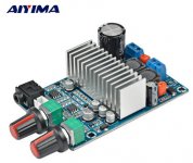
2) XH-M590 + AIYIMA TPA3116 Subwoofer board + I build a common case (3d print).
3) +1: What is your recommendation for 2.1 speaker system?
What is your opinion?
gsc73
Dear All,
First of all, I wish you a Happy New Year!
Some of you could follow my procedure to trying to fix my 2.1 amplifier board that was not successful 🙁.
So, I decided to buy another board but I would like to be more careful. I looked for recommendations in this thread but I found only stereo boards: XH-M590 by FauxFrench. In his descriptions and other recommendations, I found an interesting guideline: the simple, basic boards are better than complicated boards with BT functions and/or 2.1 channels, because there are less parts on the simple boards, so easier to fix any problem and there is less chance of failure – this statement is logical and I agree with it. BUT I have a 2.1 speaker system and I want to use it. I think I have two (+1) options:
1) This 2.1 “final” amplifier without BT. This board seems to Breeze 2.1 on the board page. I can imagine it will be OK.
2) XH-M590 + AIYIMA TPA3116 Subwoofer board + I build a common case (3d print).
3) +1: What is your recommendation for 2.1 speaker system?
What is your opinion?
gsc73
Attachments
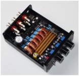
Hi GSC73,1) This 2.1 “final” amplifier without BT. This board seems to Breeze 2.1 on the board page. I can imagine it will be OK.
2) XH-M590 + AIYIMA TPA3116 Subwoofer board + I build a common case (3d print).
3) +1: What is your recommendation for 2.1 speaker system?
gsc73
1) has a fixed frequency for the subwoofer, depending on how high that is (usually around 150Hz) it could make the position of the subwoofer audible.
2) you'll need an additional stereo sub for L&R, but you'll have the benefit of being able to adjust the volume of the sub and satellites to make them blend.
3) I've recently assembled this one: Aiyima Gemonteerd Hifi Digitale Versterker TPA3116D2 2.1 High Power Board 12 24V Subwoofer Bass Board|bass board|power amplifiertpa3116d2 2.1 - AliExpress
It works (and sounds!) really well, due to the separate controls for the sub crossover frequency, volume and separate master volume.
Regards, Jan.
Last edited:
What is your opinion?
gsc73
There is one of these headed my way, am hoping it’s a decent board.
Bluetooth 5.0 Power Amplifier Board 2x60W Stereo HiFi Sound Mini Audio Amplifier | eBay
The chip has balanced inputs. Each must be coupled with a capacitor - hence the four pieces. On your board with single-ended inputs the cold inputs are grounded (via the coupling caps).
Thanks very much.
I have tried my modded XH-M590 with my test system using an MP3 player and it sounds fine, powerful and clear. When I use it in my main system I am getting some distortion. I removed the 75k gain resistors to reduce hiss. Am I right to assume that the pads left do not need to be bridged? I have not seen this suggested in the previous posts.
Best wishes for the New Year.
Table 1 and Figure 27 of the TI datasheet https://www.ti.com/lit/ds/symlink/tpa3116d2.pdf .
We aim for 20dB gain and "Master". R2 (the 75K) should be changed to OPEN and R1 (the 47K) should be changed to 5.6K. You could change R1 into 5.6K as proposed but it requires you to have and solder-in a very small SMD resistor. Normally, the 47K initially mounted is sufficient to pull pin 8 to ground, such as 5.6K would do, and you get 20dB gain without having to handle R1.
No, the pads left should not be bridged. If you bridge the pads, you would enter the "Slave" settings.
Distortion: The advantage of a SmartPhone is that it is potentially floating when not charging. Therefore easy to use as source. If your present main-system source work well with other amplifiers but not the XH-M590, it is likely that your source is missing AC coupling capacitors (to separate different DC-levels) at the output. Please try first to turn your main source ON, without music, and measure the DC voltage level at the two outputs from the source.
Last edited:
Best wishes for the New Year.
Table 1 and Figure 27 of the TI datasheet https://www.ti.com/lit/ds/symlink/tpa3116d2.pdf .
We aim for 20dB gain and "Master". R2 (the 75K) should be changed to OPEN and R1 (the 47K) should be changed to 5.6K. You could change R1 into 5.6K as proposed but it requires you to have and solder-in a very small SMD resistor. Normally, the 47K initially mounted is sufficient to pull pin 8 to ground, such as 5.6K would do, and you get 20dB gain without having to handle R1.
No, the pads left should not be bridged. If you bridge the pads, you would enter the "Slave" settings.
Distortion: The advantage of a SmartPhone is that it is potentially floating when not charging. Therefore easy to use as source. If your present main-system source work well with other amplifiers but not the XH-M590, it is likely that your source is missing AC coupling capacitors (to separate different DC-levels) at the output. Please try first to turn your main source ON, without music, and measure the DC voltage level at the two outputs from the source.
Best Wishes to you too. Thanks for your response. I am not fazed by SMD soldering. I will measure the DC voltage level as you suggest.
- Home
- Amplifiers
- Class D
- TPA3116D2 Amp