Hello FauxFrench,
Thanks for your message good of you. I did put 12V 8.5 Amps in the post above, it was a really cheapo effort at £9. My speakers are 4.0 Ohm Mark Audio CHP-70's.
Cheers - Jem
Thanks for your message good of you. I did put 12V 8.5 Amps in the post above, it was a really cheapo effort at £9. My speakers are 4.0 Ohm Mark Audio CHP-70's.
Cheers - Jem
12V is fine for a start.
Never try a bicycle in unknown condition on a steep downward slope. Try it slowly on a plane surface and when you know it works well, take it for the slopes.
12V supply causes less damage than 24V should it happen.
Never try a bicycle in unknown condition on a steep downward slope. Try it slowly on a plane surface and when you know it works well, take it for the slopes.
12V supply causes less damage than 24V should it happen.
my tp3116 amp....
the board......https://shopee.ph/product/201331797...Vsxt6fcSbot1Vm5CrUkXGECiKH4cFi8Xm12MwyOAd0upY
the psu......https://shopee.ph/SMPS-Module-HY24-...BksMcJCc8fsCmOEoWq6X8DXSMEFAhBEOF5j6sy2Y-svfk
the board......https://shopee.ph/product/201331797...Vsxt6fcSbot1Vm5CrUkXGECiKH4cFi8Xm12MwyOAd0upY
the psu......https://shopee.ph/SMPS-Module-HY24-...BksMcJCc8fsCmOEoWq6X8DXSMEFAhBEOF5j6sy2Y-svfk
Attachments

It has 5 soldering-lugs, not 5 different connection terminals...
Thanks @FauxFrench !
Yeah, realized my mistake when I started looking into it.
Will remove the heatsink and see what's underneath to gauge whether I have the ability to replace the resistors. Will check back to make sure I'm able to identify which resistors to replace and at what values.
@FauxFrench
removed the heatsink and here's what I got (see pic). sooo... what do I do again? apologies for my ignorance.
* update:
saw a video of a different board suggesting:
1. remove R3
2. replace R4 with 5K6
would this be correct?
removed the heatsink and here's what I got (see pic). sooo... what do I do again? apologies for my ignorance.
* update:
saw a video of a different board suggesting:
1. remove R3
2. replace R4 with 5K6
would this be correct?
Last edited:
@phofman
sorry, didn't realize your post was addressed to me.
yeah, im using the board more as a learning tool since i'm just starting out. will probably get a better one once i have a deeper understanding of how this stuff works. the rest of the components i used were mostly just stuff i already had on hand (my case, for instance, is an old hdd enclosure. speaker terminals from an abandoned speaker project, etc.)
I'm using an old Arcam iPod dock (irDock) as my source and a 12V 3A power brick.
@FauxFrench
removed the heatsink and here's what I got (see pic). sooo... what do I do again? apologies for my ignorance.View attachment 855528
* update:
saw a video of a different board suggesting:
1. remove R3
2. replace R4 with 5K6
would this be correct?
Many thanks for the photo.
Could you please tell me the three numbers written on R3 and R4. I cannot read them from the photo.
Please turn the amplifier board around and take (and post) a photo of the rear side of the board.
@FauxFrench
R3 : 753
R4 : 473
So if Im understanding it correctly, my board's gain is set at 36db? I'm assuming:
Mode: Master (how to tell?)
R4 to GND
R3 to GVDD
Will post a picture of the bottom of the board tomorrow since I'm home for the day. posting instead a cropped pic of R3 and R4
R3 : 753
R4 : 473
So if Im understanding it correctly, my board's gain is set at 36db? I'm assuming:
Mode: Master (how to tell?)
R4 to GND
R3 to GVDD
Will post a picture of the bottom of the board tomorrow since I'm home for the day. posting instead a cropped pic of R3 and R4
75K and 47K. Section 7.3.1 of the datasheet ( https://www.ti.com/lit/ds/symlink/tpa3118d2.pdf?ts=1593110803397&ref_url=https%253A%252F%252Fwww.google.fr%252F ). Master, 36dB gain. If R3 (75K) is removed, the gain is reduced to 20dB and the hiss is much less. R4 need not be changed to 5K6.
Last edited:

If R3 (75K) is removed, the gain is reduced to 20dB and the hiss is much less. R4 need not be changed to 5K6.
awesome, thanks again! i'll check back in once i get to remove R3. will probably keep the trimmer pots first since they are already 10K (not 50K as was the case in other boards). will change it if hiss persists.
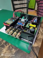
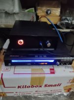
Hello all
My amp arrived today Sunday! Bought on ebay delivered by Amazon!!

This is my little listening room at the back of the garage.
The PS is a cheapo 12v 8.5 Amp smps
The board is the XH-M590
If I may, a question? is it possible to have just one channel working, I have tried just one connected to my speakers, no sound at all, with both connected it's fine. I want to do a switched comparison from a listening position with my 3886 with both in mono.
Upon switching on no 'PfffT' at all, switching off just a mild 'pttt'.
No other interference or other odd noises at all.
A hiss through the speakers but as far as I can tell goes with a signal.
Hello FauxFrench
I will be taking some pics of both sides for you I will put them up tomorrow.
Cheers - Jem
My amp arrived today Sunday! Bought on ebay delivered by Amazon!!
This is my little listening room at the back of the garage.
The PS is a cheapo 12v 8.5 Amp smps
The board is the XH-M590
If I may, a question? is it possible to have just one channel working, I have tried just one connected to my speakers, no sound at all, with both connected it's fine. I want to do a switched comparison from a listening position with my 3886 with both in mono.
Upon switching on no 'PfffT' at all, switching off just a mild 'pttt'.
No other interference or other odd noises at all.
A hiss through the speakers but as far as I can tell goes with a signal.
Hello FauxFrench
I will be taking some pics of both sides for you I will put them up tomorrow.
Cheers - Jem
Is it possible to have just one channel working? BOTH OUTPUTS NEED A LOAD (when turned ON)! Else, you risk damaging the board. With both outputs loaded, eventually one output with an 8 Ohm dummy power-resistor, you can put signal on only one intput.
Hello FauxFrench,
Many thanks for your good advice I'm grateful to you.
I do have 2 - 3.9 Ohm 10 Watt resistors in concrete would they be OK in series?
Cheers - Jem
Many thanks for your good advice I'm grateful to you.
I do have 2 - 3.9 Ohm 10 Watt resistors in concrete would they be OK in series?
Cheers - Jem
Two 3.9 Ohm 10W in series will do fine.
NB: Check the temperature of the power resistors from time-to-time.
NB: Check the temperature of the power resistors from time-to-time.
Last edited:
Thanks FauxFrench
Good of you to respond so quickly I'll pop out and give them a go straightaway.
I'll set up my input leads and the DPDT switch tomorrow I would like to do a comparison with my 3886 both before doing the mods and afterwards.
Initial listening makes me think this amplifier is very good indeed, glad I found this thread and you 🙂
Cheers - Jem
Hello FauxFrench
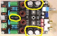
Here are the pics, I took the heat sink off because there are some smd parts under it.
Front
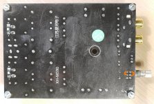
Reverse
1000px long side large pics download from Google Drive
Front
3116BoardFront1000px.jpg - Google Drive
Reverse
3116BoardReverse1000px.jpg - Google Drive
Parts
From the right
Brown Caps - Numbers hidden
Blue Caps - 2E103 10 nF
Green Caps - 684k2W 680 nF
Black Caps - 470 uF 50V 4 off
Ditto - 100 uF 35V 2 off
Orange - 1.0 uF 4 off
Hope this helps
Cheers - Jem
Here are the pics, I took the heat sink off because there are some smd parts under it.
Front
An externally hosted image should be here but it was not working when we last tested it.
Reverse
An externally hosted image should be here but it was not working when we last tested it.
1000px long side large pics download from Google Drive
Front
3116BoardFront1000px.jpg - Google Drive
Reverse
3116BoardReverse1000px.jpg - Google Drive
Parts
From the right
Brown Caps - Numbers hidden
Blue Caps - 2E103 10 nF
Green Caps - 684k2W 680 nF
Black Caps - 470 uF 50V 4 off
Ditto - 100 uF 35V 2 off
Orange - 1.0 uF 4 off
Hope this helps
Cheers - Jem
Many thanks for the photos. Can't make high-res photos work.
My changes:
1) The two "753" (75K) resistors are removed in order to reduce the gain (and hiss) to 20dB.
2) The diode marked with yellow is bridged with a 0.75mm2 wire. Loss of wrong polarity protection but improved effect of external power rail decoupling capacitor(s).
3) The four 470uF/50V decoupling capacitors (marked with yellow) are replaced by 2200uF/35V low ESR capacitors.
4) Rear side. Two small 4K7 resistors are connected as show with orange lines.
5) The rear side of the board is cleaned with isopropyl alcohol. Use a soft brush and hold the board vertically such that the alcohol drips off in a corner.
6) Use a bit of thermally conductive compund when putting back the heatsink.
I have some 6 different TPA3116 boards and this one plays the best. On the output of my power adapter I have some further 10000uF.
Attachments
Last edited:
Good morning FauxFrench,
Many thanks for the list of modifications good of you to do it so precisely.
I've ordered four 2200 uF Caps from Cricklewood Electronics.
I also found the data sheet and have printed off a couple of pages, your quite right about the board following TI's design. I looked at Table 1 and the Gain chart and see that 20dB is 5.6k and the 75k is open as you suggest. I've watched a video on YT about removing and replacing SMD's, I've ordered a range of 0603's to suit all the gain settings. If I am successful at removing the 75k I'll try removing the 47k and soldering in a 5.6k.
If that works I'll try some of the other settings to see at what stage the hiss disappears.
Further Google searches reveal replacing the pot with a 10k, if I can remove that, I do have a solder pump, I'll use two 10k pots and a separate switch.
I'll also do the power input bypass and I'll remove the RCA connectors.
Thanks for the tip about the concrete resistors, in the event they didn't even get warm. My speakers are 4 Ohm 86dB so the 12V power supply is ample, 40 Watts output from looking at the data sheet graph.
For what it is the amp is amazing!
Cheers - Jem
Hi Jem,
The gain of the TPA3116 is decided at start-up where a simple ADC inside the chip measures the voltage at pin 8 and decides for "master" or "slave" and the gain level (voltage level coding). When you remove the 75K, pin 8 is pulled to ground through 47K. Thus, 0V on pin 8. If you replace the 47K with 5K6, pin 8 is pulled to ground through 5K6. Hence, still 0V on pin 8. For your training in handling SMD components you can change the 47K to 5K6 but you will not notice a difference.
If you can clean all the mounting holes for the potentiometer, you can change the volume potentiometer (8 pins). But, the mounting holes are through-plated and I had major problems cleaning such plated holes. I risked damaging the PCB tracks and pads instead. Therefore, I kept the potentiometer and mounted the 4K7 as a compensation.
When I ordered my XH-M590, I had to wait 6 months (!) before it arrived. Did you get yours within reasonable time?
Greetings, FF
Hello FauxFrench,
Many thanks for the additional information I am so grateful.
I tried the 1st mod, that of removing both the 75k (753) resistors. No hiss not even a whisper and if I get my ear close to a speaker there is a faint mains hum with the pot on full and then set at a level of high volume, nothing at all.
Thinking that the volume with my 12V supply and 4 Ohm speakers might diminish with the 20dB gain, I was a bit concerned about doing it, I'm completely wrong I'm pleased to say, very loud indeed is about still about 1/3 rotation of the pot.
The board arrived in three days I bought it from a UK eBay listing, oddly though it was delivered by Amazon on Sunday!
Next up the 2200 uF 35V Caps when they arrive.
I had a thought about the pot and the switch, I have large 17" x 12" x 2" (425 x 300 x 50) wooden boxes that I put my amps in and need to have inputs and outputs on the panels. If I were to turn the switch on, set the pot at full volume, take leads from under the board to, two pots and one switch would that work?
Cheers - Jem
- Home
- Amplifiers
- Class D
- TPA3116D2 Amp