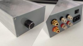
XH-M590 Many postings ago I was asked which TPA3116 board I found was the best. I made a brief study from photos of different boards and concluded that the XH-M590 board seemed to be one of the best ( KYYSLB DC12 24V High Power 100W*2 TPA3116D2 Digital Power Amplifier Board XH M590 Home Audio Amplifier Board 2~8 Ohms|Amplifier| - AliExpress ): Good output filter components, dual TPA3116 chip with a large heatsink fastened with a screw, decent power line decoupling with possibility for upgrade, good connectors and film input capacitors.
An issue was that the XH-M590 board exists in two version of which a less attractive version has two smaller heatsinks glued to the TPA3116 ICs and uses non-standard squared power-rail decoupling capacitors. I managed to find the version I preferred and ordered it on 30.11.2019. Tracking the parcel with the board went well until I was told (E-mail) that the board had just been delivered to me which it had not. I investigated the fate of my parcel but found nothing precise and in the end I kindly got reimbursed. I forgot about the board. But, Monday 8 June 2020 the board somehow made it to my mailbox, in original packing, after more than 6 months!
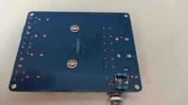
Now I will briefly describe my first test results because the board actually is one of the best considering the price (from a bit above 10 Eur with sending costs).
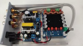
The board layout is neat and the PCB of good quality. The mounting of components on the board is quite good, and I only re-did a few solderings.
For power-rail decoupling, four 470uF/50V capacitors are used. While 50V voltage rating is unnecessarily generous, 4x470uF is not much if benefit is taken of the dual chip design with low impedance loads. Luckily the initial decoupling capacitors are physically rather short and at ”fat” such that there is good space for larger decoupling capacitors. After a very brief check with a 12V supply that the initial board functioned, the initial decoupling capacitors were changed to four 2200uF/35V Nichicon capacitors. If you use low impedance speakers, the DC input connector (for power supply) may be bypassed by supply wires soldered directly to the terminals below and the reverse-polarity-protection diode short-circuited.
With a 20V/24V power source, the board plays very well. Good vocals and bass. The gain is for most use (too) high and without music, I believe I can hear a bit of hiss with the volume potentiometer in mid-position. I will reduce the gain to 20dB and mount two 4K7 resistors on the potentiometer output which should certainly remove any hiss.
From my test of the board, I can only recommend it as one of the best for a moderate price.
For less experienced members, such a basic board (stereo) without a buffer amplifier at the input and no sophisticated control of activate/mute functionality can be an important advantage. In case a basic board does not function well, the circuit implemented is close to the circuit recommended in the datasheet. The moment 2.1 features (filters), pre-amp circuits, numerically controlled input selection circuits and in particular BlueTooth circuits are included, much goes wrong in these circuits and we on the forum have no idea how these circuits are designed and implemented. Therefore, it is difficult to help you find errors in such complex boards. Keep it simple and use basic boards. If needed, use separate boards for filters, pre-amp circuits and BlueTooth – this way we can decide which boards work and which not.
An issue was that the XH-M590 board exists in two version of which a less attractive version has two smaller heatsinks glued to the TPA3116 ICs and uses non-standard squared power-rail decoupling capacitors. I managed to find the version I preferred and ordered it on 30.11.2019. Tracking the parcel with the board went well until I was told (E-mail) that the board had just been delivered to me which it had not. I investigated the fate of my parcel but found nothing precise and in the end I kindly got reimbursed. I forgot about the board. But, Monday 8 June 2020 the board somehow made it to my mailbox, in original packing, after more than 6 months!
Now I will briefly describe my first test results because the board actually is one of the best considering the price (from a bit above 10 Eur with sending costs).
The board layout is neat and the PCB of good quality. The mounting of components on the board is quite good, and I only re-did a few solderings.
For power-rail decoupling, four 470uF/50V capacitors are used. While 50V voltage rating is unnecessarily generous, 4x470uF is not much if benefit is taken of the dual chip design with low impedance loads. Luckily the initial decoupling capacitors are physically rather short and at ”fat” such that there is good space for larger decoupling capacitors. After a very brief check with a 12V supply that the initial board functioned, the initial decoupling capacitors were changed to four 2200uF/35V Nichicon capacitors. If you use low impedance speakers, the DC input connector (for power supply) may be bypassed by supply wires soldered directly to the terminals below and the reverse-polarity-protection diode short-circuited.
With a 20V/24V power source, the board plays very well. Good vocals and bass. The gain is for most use (too) high and without music, I believe I can hear a bit of hiss with the volume potentiometer in mid-position. I will reduce the gain to 20dB and mount two 4K7 resistors on the potentiometer output which should certainly remove any hiss.
From my test of the board, I can only recommend it as one of the best for a moderate price.
For less experienced members, such a basic board (stereo) without a buffer amplifier at the input and no sophisticated control of activate/mute functionality can be an important advantage. In case a basic board does not function well, the circuit implemented is close to the circuit recommended in the datasheet. The moment 2.1 features (filters), pre-amp circuits, numerically controlled input selection circuits and in particular BlueTooth circuits are included, much goes wrong in these circuits and we on the forum have no idea how these circuits are designed and implemented. Therefore, it is difficult to help you find errors in such complex boards. Keep it simple and use basic boards. If needed, use separate boards for filters, pre-amp circuits and BlueTooth – this way we can decide which boards work and which not.
Last edited:
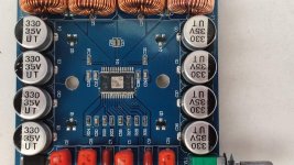
XH-M590 I just finished the modifications mentioned in the previous posting and the results were as expected. This version of the XH-M590 is set for a gain of 36dB using a 75K and a 47K resistor (master, 36dB). This setting is the same for both TPA3116 chips such that the two chips are not synchronized but run at close to 400KHz (carrier frequency) individually.
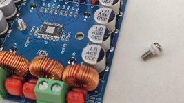
Changing the gain to 20dB (as master) just requires the two 75K resistors (marked with "753") to be removed. That requires the heatsink to be removed. Removing the heatsink I realized that no thermal paste was used between the TPA3116 ICs and the heatsink. If you remove the heatsink and find that no thermal paste is used, give it a little on both ICs before putting the heatsink back.
Changing the gain to 20dB (as master) just requires the two 75K resistors (marked with "753") to be removed. That requires the heatsink to be removed. Removing the heatsink I realized that no thermal paste was used between the TPA3116 ICs and the heatsink. If you remove the heatsink and find that no thermal paste is used, give it a little on both ICs before putting the heatsink back.
Thanks a lot for the great review. And that board looks easy to modify for the balanced operation to avoid the ground loops too.
FauxFrench,
What do you think of such a board? Only recently I saw this model on sale.
KYYSLB 2019 24V 3A 50W+50W TPA3116 Two channel stereo digital power amplifier board|Amplifier| - AliExpress
What do you think of such a board? Only recently I saw this model on sale.
KYYSLB 2019 24V 3A 50W+50W TPA3116 Two channel stereo digital power amplifier board|Amplifier| - AliExpress
FauxFrench,
What do you think of such a board? Only recently I saw this model on sale.
KYYSLB 2019 24V 3A 50W+50W TPA3116 Two channel stereo digital power amplifier board|Amplifier| - AliExpress
I think ->
Good: Film input capacitors, good connectors, output filter chokes, size of heatsink.
Reasonable: Single chip handling less output current, decent output filter capacitors, Sanwu designs are generally working.
Poor: 8x330uF power-rail decoupling that is very difficult to replace, heatsink seems glued to the chip and therefore difficult to remove and put back.
For the same cost I would prefer the XH-M590.
Was finally able to build my amp. Will skip the pictures because it's not pretty at all but am quite happy as it was my first attempt. Thanks to those who took the time to answer my questions!
As expected, I get a pop when I turn it on and a soft hiss while its running. Can both of these be addressed by replacing the potentiometer with a 10K logarithmic that can also be used as the power switch? I read that the pop can be minimized by turning the unit on with the volume all the way down and that the hiss can be addressed by replacing the volume pot/s. Attached is a pic of the board Im using. It has built in potentiometers for Left and Right channels. Not sure though if it is for Gain or Volume. How can I tell?
As expected, I get a pop when I turn it on and a soft hiss while its running. Can both of these be addressed by replacing the potentiometer with a 10K logarithmic that can also be used as the power switch? I read that the pop can be minimized by turning the unit on with the volume all the way down and that the hiss can be addressed by replacing the volume pot/s. Attached is a pic of the board Im using. It has built in potentiometers for Left and Right channels. Not sure though if it is for Gain or Volume. How can I tell?
"POP" has got nothing to do with the potentiometer value. 10K will absolutely help on hiss, 4K7 even more. Hiss can also be helped by lowering the TPA3116 gain. For your board it should be quite easy as the heatsink seems fixed with screws.
Gain and volume are two parameters relating to the same matter. With a volume potentiometer, you change the gain from the board input to the board output by making a variable voltage divider. However, the TPA3116 gain remains fixed, independent on the position of the volume potentiometer.
Gain and volume are two parameters relating to the same matter. With a volume potentiometer, you change the gain from the board input to the board output by making a variable voltage divider. However, the TPA3116 gain remains fixed, independent on the position of the volume potentiometer.
@FauxFrench
thanks for the reply!
As for "pop", I was under the impression that it would be eliminated if the volume were turned down prior to powering up the unit. This is why I thought of incorporating a potentiometer that turns the unit on as it powers up (similar to those in built up t-amps).
I guess I'll go ahead and replace the pots first and see if that takes care of the hiss.
The "POP" appears because when the amplifier is un-muted by the control circuit, there is still a small voltage difference between the two (BTL) output lines. Moderate "POP" is not a problem for the speakers
@FauxFrench
oh ok! the pop isnt really that bad in my case. im actually more keen on fixing the hiss. trying to figure out how to wire it since the 4k7 pot has five pins and my board's volume control has 2 trimmer pots (one left, one right) with 3 pins each.

oh ok! the pop isnt really that bad in my case. im actually more keen on fixing the hiss. trying to figure out how to wire it since the 4k7 pot has five pins and my board's volume control has 2 trimmer pots (one left, one right) with 3 pins each.
It has 5 soldering-lugs, not 5 different connection terminals. If you look at the potentiometer, the two front sets of soldering-lugs are connected two-and-two. I am pretty sure it is a multi-turn wire-wound potentiometer. Such are often meant for measuring instruments and precision power supplies but not really suited for audio. Try searching with the word "B5K" on AliExpress and you find better suited potentiometers.
* Power terminals very close to the high-impedance inputs, the unshielded trimmers are right next to them.
* Input cinches right next to output terminals, long unshielded wires out of the shielded cable
* The rather long shielded cable along the output stage.
* Unshielded case
* Very likely low-quality SMD input coupling capacitors, the plane below them is likely a noisy power trace from the protection diode to the chip.
I would dump the board and get the XH-M590 FauxFrench recommends. The onboard pot could be used for volume control, either as is, or extracted to a place where it's reachable.
What input source do you use, what is the power supply?
XH-M590The gain is for most use (too) high and without music, I believe I can hear a bit of hiss with the volume potentiometer in mid-position. I will reduce the gain to 20dB and mount two 4K7 resistors on the potentiometer output which should certainly remove any hiss
Dear FauxFrench,
This board has a potentiometer with a resistance of 50 kOhm. At a gain level of 26dBa do you recommend leaving it or replacing it with a lower resistance? Of course it is planned to install a resistance of 4.7 kOhm at the outputs of the potentiometer.
Dear FauxFrench,
This board has a potentiometer with a resistance of 50 kOhm. At a gain level of 26dBa do you recommend leaving it or replacing it with a lower resistance? Of course it is planned to install a resistance of 4.7 kOhm at the outputs of the potentiometer.
With a 4K7 resistor at the output of the potentiometer, I do not change the potentiometer. If you do change the potentiometer, you may get a more smooth increase of the sound level when you turn-up the potentiometer. For me that is not important as I have another volume potentiometer at the pre-amp.
Try with the 4K7 resistor for a start and see if you are happy with this solution.
For my amplifier I chose a board https://aliexpress.ru/item/33057102013.html because I was limited by the size of the case.
The board has banging when turned on and off but they are low expressed.
With the help of a heat gun and physical effort I removed the radiator and installed it on the screws.
Then set the 4K7 resistance at the output of the potentiometer.
As a result the hiss became barely noticeable and the quality of the playback completely satisfied me.
Assembled in the case of the board and power supply for 24V.
Attachments
Really nice work! Amplifier with good output filter components, foil input capacitors and set correctly to 26dB gain as master. Now it is only to enjoy the sound. 
XH-M590 Many postings ago I was asked which TPA3116 board I found was the best. I made a brief study from photos of different boards and concluded that the XH-M590 board seemed to be one of the best ( KYYSLB DC12 24V High Power 100W*2 TPA3116D2 Digital Power Amplifier Board XH M590 Home Audio Amplifier Board 2~8 Ohms|Amplifier| - AliExpress )
Hello all and Hello FauxFrench
I tried Aliexpress but couldn't get past the 'put your address in' instead of adding 'England' from a drop down it linked to another page on the site. Blast it!!
I searched for a couple of days and then there it was
An externally hosted image should be here but it was not working when we last tested it.
From a guy in London and on eBay 3 day delivery he says.
I'll change the capacitors as per FauxFrench's recommendations, some of the other stuff I didn't understand I do hope you won't mind me asking some (daft) questions later.
One I thought of though .... will I need a preamp?
Cheers and thanks for the clarity in this thread, this Class D caper's utterly new to me.
Jem
Hello all and Hello FauxFrench
I tried Aliexpress but couldn't get past the 'put your address in' instead of adding 'England' from a drop down it linked to another page on the site. Blast it!!
I searched for a couple of days and then there it was
From a guy in London and on eBay 3 day delivery he says.
I'll change the capacitors as per FauxFrench's recommendations, some of the other stuff I didn't understand I do hope you won't mind me asking some (daft) questions later.
One I thought of though .... will I need a preamp?
Cheers and thanks for the clarity in this thread, this Class D caper's utterly new to me.
Jem
When you receive the board, take a photo of the rear side and we can give you guidance on what to modify.
Do a first test with a 12V power adapter before modifying anything ("as is"). You do not need a pre-amp. You can use the headphone output from your smartphone directly.
Hello FauxFrench,
Thanks for the offer of some assistance I'm grateful to you.
My input will be from an LG CD/DVD player. I bought a Philips CD723 second hand some years ago and did the mods from the DecDun site, I thought it was great! Recently I started doing my own CD's and it said rather nastily, "This disc has not been finalised", which it had! I typed the phrase into Google and came up with someone who'd bought a cheap CD/DVD player and said it was very good indeed.
I went to our local Argos and paid peanuts for my LG, it makes the CD723 sound like Monty Python's Parrot, I was amazed and it'll play anything I bung into it.
The analog output is 2V RMS 600 Ohms.
As soon as I get the TPA3116 board I'll test it and then take the pics and post them here. I have this 12V 8.5 Amp SMPS

I'll use this for the test.
Cheers -Jem
Thanks for the offer of some assistance I'm grateful to you.
My input will be from an LG CD/DVD player. I bought a Philips CD723 second hand some years ago and did the mods from the DecDun site, I thought it was great! Recently I started doing my own CD's and it said rather nastily, "This disc has not been finalised", which it had! I typed the phrase into Google and came up with someone who'd bought a cheap CD/DVD player and said it was very good indeed.
I went to our local Argos and paid peanuts for my LG, it makes the CD723 sound like Monty Python's Parrot, I was amazed and it'll play anything I bung into it.
The analog output is 2V RMS 600 Ohms.
As soon as I get the TPA3116 board I'll test it and then take the pics and post them here. I have this 12V 8.5 Amp SMPS
I'll use this for the test.
Cheers -Jem
Hi Jem,
2V rms / 600 Ohm should be fine.
For the power supply, it looks OK but I get no information about the voltage.
2V rms / 600 Ohm should be fine.
For the power supply, it looks OK but I get no information about the voltage.
- Home
- Amplifiers
- Class D
- TPA3116D2 Amp