What are the current "best recommendation" for a plain stereo 3116 amplifier board (no need for 2+1/ bluetooth or other similar). I am happy about the YJ version TPA3116D2 Boards, with the DIY snubber mod, but cannot find this or variants of it anywhere. Any recommendation where to find this, or someting similar/ better?
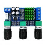
This is my favoured bare 3116, can be improved by changing the caps to OSCONs and adding and RC Snubbers:
Assembled TPA3116 class D amplifier board 50W+50W (green pcb) | eBay
Assembled TPA3116 class D amplifier board 50W+50W (green pcb) | eBay
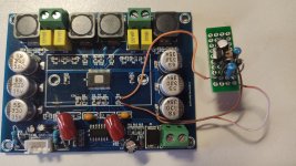
Well; I have one more question. I have attached two photos of the amp I’m listening at the moment (the red one).
The gain is somehow low but I have no idea how to calculate it from those two resistors. I couldn’t find some informations in the data sheet how to calculate gain.
R2= 75k ohm
R1= 4.7k ohm
By the way; my other amp (the blue one) has 'by the book' gain of 32dB (R2= 100k ohm ; R1= 39k ohm).
Regards
The gain is somehow low but I have no idea how to calculate it from those two resistors. I couldn’t find some informations in the data sheet how to calculate gain.
R2= 75k ohm
R1= 4.7k ohm
By the way; my other amp (the blue one) has 'by the book' gain of 32dB (R2= 100k ohm ; R1= 39k ohm).
Regards
Attachments

Last edited:
This is an amp, not a heater. It is class D which means high efficient, cool running. Ask your self, what do you win if you make the heater coil bigger?
There is a severe mistake in the construction of this amp that leads to in audible oscillation, which heats up the coil.
If you know how to use an ampere meter, you can see how much current it takes. Then compare to the data sheet.
This is, if you like playing with amps. An experienced amp builder can alter the construction to get rid of the problem.
If you only want to use such a module as an amp, throw it in the bin and buy one that is recommended in this forum.
By the way, you can not use such an amp outside of a metal case, for safety and EMF reasons. You probably don´t care, like most, I know. Depends on your country what happens if you run such an transmitter and disturb air traffic.
what do you mean in the last paragraph, can running it outside a Faraday case disturb air traffic. its an amp why u call it an transmitter? i get the use of the metal case for grounding and to keep out EM waves and noise.
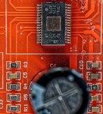
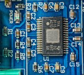
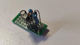
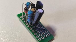
Well; I have one more question. I have attached two photos of the amp I’m listening at the moment (the red one).
The gain is somehow low but I have no idea how to calculate it from those two resistors. I couldn’t find some informations in the data sheet how to calculate gain.
R2= 75k ohm
R1= 4.7k ohm
By the way; my other amp (the blue one) has 'by the book' gain of 32dB (R2= 100k ohm ; R1= 39k ohm).
Regards
Hi Igla,
It is Table 1 and Figure 27 in the datasheet ( http://www.ti.com/lit/ds/symlink/tpa3116d2.pdf ).
They made a mistake when they put components on the board.
R4 is 4K7 ("472") but should have been 47K ("473") for a gain of 36dB. At present you have a gain of 20dB but less hiss.
The gain can only be adjusted in 4 steps as shown in Table 1.
Hi Faux French;
I don't know if they made a mistake but the gain is low and I didn't know how to calculate it.
There is no such combination in the table so how do you know the gain is 20dB?
Does this mean my amp should not be working with resistors 75k and 4.7k?
Regards;
I don't know if they made a mistake but the gain is low and I didn't know how to calculate it.
There is no such combination in the table so how do you know the gain is 20dB?
Does this mean my amp should not be working with resistors 75k and 4.7k?
Regards;
Hi Faux French;
I don't know if they made a mistake but the gain is low and I didn't know how to calculate it.
There is no such combination in the table so how do you know the gain is 20dB?
Does this mean my amp should not be working with resistors 75k and 4.7k?
Regards;
Hi Igla,
Table 1 in the datasheet shows 8 different combinations of resistors that work as voltage dividers of the voltage GVDD on pin 7. During start-up, the TPA3116 chip looks at the voltage on pin 8 (GAIN/SLV) and decides which one of the 8 possibilities you want for its operation. The voltage at pin 8 is the GVDD voltage divided by the two resistors (GVDD is typically 6.9V as specified in the datasheet). The TPA3116 chip knows that you have 8 different possibilities (8 voltage ranges) that each correspond to one of the operational modes listed in Table 1. The TPA3116 chip does not try to read the values of the two resistors but only cares about the voltage at pin 8. The datasheet does not describe the 8 different voltage ranges but gives you values of the resistors in the voltage divider such that you hit well inside each of the 8 possibilities. That is the easiest for the users.
This is not feedback in the sense you are used to from OP-AMPs or chip-amps, this is voltage coding that is only read at start-up.
True, there is no 4K7/75K combination in Table 1. There is, however, a 47K/75K combination for "Master - 36dB gain". Sounds close, doesn't it?
GVDD split between 4K7 (low) and 75K (high) results in 5.9% of the input voltage (GVDD).
GVDD split between 20K (low) and 100K (high) results in 16.6% of the input voltage (GVDD). 20K/100K is 26dB gain and "Master/BTL" in Table 1.
But 4K7/75K gives much less output voltage (on pin 8) than 20K/100K which is 26dB gain. Much less voltage on pin 8 means at least one step lower in gain. The lowest gain-step is 20dB and this is what you have.
I am pretty sure that the intention was 47K/75K and 36dB gain, as shown in Table 1. Someone made a mistake and the resistors became 4K7/75K such that you only have 20dB gain.
Last edited:
Thanks for the explanation FauxFrench.
Now I understand.
This gain of 20dB is more then enough for my 92dB/35W full range loudspeakers and my source.
But for some other applications I have in mind I could change the gain and now I know, how this works.
Regards;
Now I understand.
This gain of 20dB is more then enough for my 92dB/35W full range loudspeakers and my source.
But for some other applications I have in mind I could change the gain and now I know, how this works.
Regards;
Member
Joined 2018

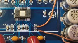
I have a different revision of the amplifier Board than the one you updated on the link.
The problems it has are similar to many tpa3116 boards: hissing and banging when turned on and off.
At first I removed the potentiometer on the input and put 4K7 resistors across the input terminals to ground as recommend FauxFrench.
Then I bypass pre-amplifier TL074. Initially the gain level was set to 26dB and this is enough for me.
All this brought tangible results and the sound quality began to suit me.
But the pop sound when the power is turned on really annoyed me.
I tried to implement CyberPit muting driver circuit (2x100W TPA3116D2 (2 chips, each in PBTL)) but it did not give any result.
Dear CyberPit, can you check my board and help with your circuit?
Used elements:
resistor 1 MOhm
resistor 10 KOhm
resistor 1 KOhm
diode 11DQ04 DO-204AL
zener diode 12V 1W (1N4742A)
transistor 2N7000 TO-92 UTC N-MOS, 60V, 0.2A, 0.4W
capacitor 3.3mkf 100V
resistor 10 KOhm
resistor 1 KOhm
diode 11DQ04 DO-204AL
zener diode 12V 1W (1N4742A)
transistor 2N7000 TO-92 UTC N-MOS, 60V, 0.2A, 0.4W
capacitor 3.3mkf 100V
Attachments

i have this amp board TPA3116 Subwoofer Amplifier Board 2.1 Channel HIFI Bluetooth AMP 2*50W+100W | eBay after some use and while not playing anything though it i can hear some static or weird noise in of the two speaks that lasts for just a a few seconds usually and comes back after a couple minutes or so. I can fix it if i shut off the amp and disconnect from the powersupply for a few seconds. What chould this be? Keep in mind that the amp is in a wooden box not grounded to anything
Member
Joined 2018
But the pop sound when the power is turned on really annoyed me.
I tried to implement CyberPit muting driver circuit (2x100W TPA3116D2 (2 chips, each in PBTL)) but it did not give any result.
Dear CyberPit, can you check my board and help with your circuit?
Used elements:resistor 1 MOhm
resistor 10 KOhm
resistor 1 KOhm
diode 11DQ04 DO-204AL
zener diode 12V 1W (1N4742A)
transistor 2N7000 TO-92 UTC N-MOS, 60V, 0.2A, 0.4W
capacitor 3.3mkf 100V
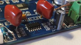
Hi randomice-San,
All of your pictures seem to good and right connected.
11DQ04 DO-204AL is schottky diode. Leak current of reverse leakage will shorten the PowerON mute duration. You'd better to change to Si Switching diode such as 1N4148.
So I will recommend you'll check the following points.
- Operating power supply voltage?
- Voltage transition of MUTE-OUT (PowerON: High --> LOW, PowerOFF: Low --> High then down)
- Still, pops? If you tie pin12(MUTE) to VCC permanently without Driver board.
Point2 Mute-OUT voltage Falls about 4 seconds after PowerUP. Raises immediately after the PowerDOWN.
Point3 There's no sound nor pops.
CyberPit
Last edited:
I have just bought one of these blue 3116 boards as in pic. There is of course a ton of hissss. The variable resistors are 10k. Would increasing the values to say 50k lessen the hiss, or should I by-pass them?
Generally, increasing the pot resistance will increase hiss, 10k should be low enough. Playing with the master/slave and gain resistors might help. There is also a superfluous opamp preamp that you can bypass.
Last edited:

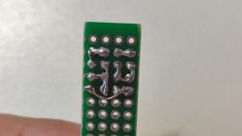
just created this board it includes the anti pup board in it if you guys need it to let me know so ill creat the Graber files and post it here, also as it is my first ever design please let me know if I'm having any mistakes if you have the knowledge
An externally hosted image should be here but it was not working when we last tested it.
- Home
- Amplifiers
- Class D
- TPA3116D2 Amp