Happy New Year everyone! If you are feeling the itch to tinker in the new year, here is something you can do.
It is based on the prototype SIT-4, which I got to hear back in Sep 2023. See here for more info. It had absolutely stunning sound and since then I've been wanting to try a version at home. Well, I finally got a bit of time over the holidays and put something together.
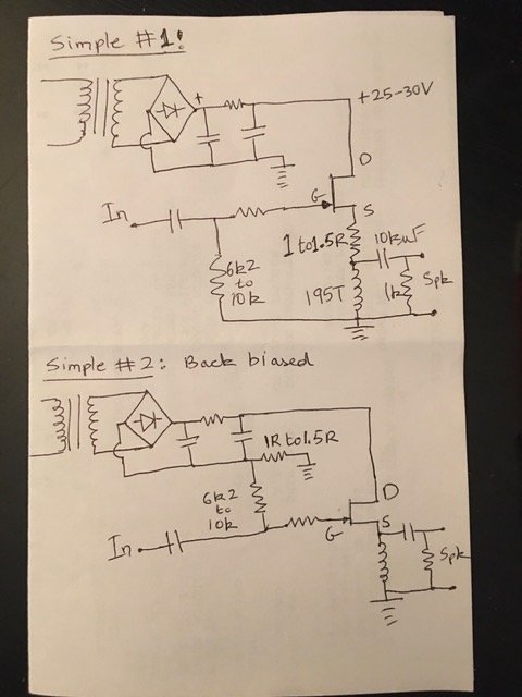
As is the way with the TDV, I went for simple: get it working first, add the bells and whistles later. The SIT-4 is a common source amp, which means the drain gets loaded, we take the output from the drain, and we get both voltage gain and current gain. The downside is more distortion than in follower mode, which Ben Mah has commented on in the past. The SIT-4 uses feedback to lower the output impedance and also the distortion. So, let's throw some feedback at it and see what happens.
I vaguely recall SIT-4 having 6 dB gain, which is 6 dB more than in follower mode, so we'll take it. That means a 2X ratio for the feedback resistors. Here is where it gets tricky. The gate of the VFET has quite a bit of capacitance. I tried 30k/60k (R2/R1) resistors and was getting poor bandwidth. So, I changed it to 3k3/6k8 and that was much better. I can say, without measurements, that the bandwidth is more than 15-20 kHz, good enough for me. One day we'll add a buffer, ala SIT-4, and get more bandwidth. For now, to get a feel for the sound, we needn't go any further than 3k3/6k8. The SCG preamp has an output impedance of less than 100 ohms and drives it just fine. Preamps with output impedances less than 300 ohms and good amount of current drive are needed. The FE 2022 should also drive it, though I haven't tried it yet.
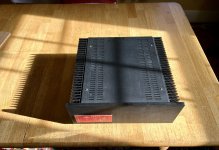
Schematic is shown below. Power supply is the usual FW style. Whatever you have for the TDV will work. Anywhere from 18-30V on the drain is fine. For setting the current, we will revisit the 'back bias' method from Post 18. Works like a charm and is super simple. The key is to connect the 0V or chassis ground to the common ground and connect R6 between that point and the power supply cap (as shown in the schematic). That generates a negative voltage which can be used to bias the gate (via R4). I am running it at 20V and 2.2A, but anywhere from 1.4-2.5A is fine, given proper heatsinking. The entire bias current will flow through R6, so it has to be rated to handle the power. For example, at 2A and 1R, the power dissipated is 2x2x1=4W, i.e., minimum 10W resistor is needed and good ventilation around the resistor.
R1 and R2 form the feedback loop. The other components are self-explanatory. I am using the 2SK2087C and I just moved some stuff around in the TDV chassis and kept the bias the same as in the follower mode.
All the usual cautions apply. These are rare devices. Double-check connections and bring it up slowly with a Variac while monitoring the current draw and gate-source voltage. One channel at a time.
How does it sound? Astonishingly good. I have horn speakers and don't need a lot of power. I am also experimenting with current source crossovers, so my speakers present a very easy load and are a good match to this common source topology. There is slightly more distortion than in follower mode, but that is not so noticeable. What it does provide is more forward throw of the soundstage. Very, very addictive. You might like it or you might want the lower distortion of the follower mode. But fun to try. Enjoy!
Thanks to Papa, as always!

It is based on the prototype SIT-4, which I got to hear back in Sep 2023. See here for more info. It had absolutely stunning sound and since then I've been wanting to try a version at home. Well, I finally got a bit of time over the holidays and put something together.
As is the way with the TDV, I went for simple: get it working first, add the bells and whistles later. The SIT-4 is a common source amp, which means the drain gets loaded, we take the output from the drain, and we get both voltage gain and current gain. The downside is more distortion than in follower mode, which Ben Mah has commented on in the past. The SIT-4 uses feedback to lower the output impedance and also the distortion. So, let's throw some feedback at it and see what happens.
I vaguely recall SIT-4 having 6 dB gain, which is 6 dB more than in follower mode, so we'll take it. That means a 2X ratio for the feedback resistors. Here is where it gets tricky. The gate of the VFET has quite a bit of capacitance. I tried 30k/60k (R2/R1) resistors and was getting poor bandwidth. So, I changed it to 3k3/6k8 and that was much better. I can say, without measurements, that the bandwidth is more than 15-20 kHz, good enough for me. One day we'll add a buffer, ala SIT-4, and get more bandwidth. For now, to get a feel for the sound, we needn't go any further than 3k3/6k8. The SCG preamp has an output impedance of less than 100 ohms and drives it just fine. Preamps with output impedances less than 300 ohms and good amount of current drive are needed. The FE 2022 should also drive it, though I haven't tried it yet.
Schematic is shown below. Power supply is the usual FW style. Whatever you have for the TDV will work. Anywhere from 18-30V on the drain is fine. For setting the current, we will revisit the 'back bias' method from Post 18. Works like a charm and is super simple. The key is to connect the 0V or chassis ground to the common ground and connect R6 between that point and the power supply cap (as shown in the schematic). That generates a negative voltage which can be used to bias the gate (via R4). I am running it at 20V and 2.2A, but anywhere from 1.4-2.5A is fine, given proper heatsinking. The entire bias current will flow through R6, so it has to be rated to handle the power. For example, at 2A and 1R, the power dissipated is 2x2x1=4W, i.e., minimum 10W resistor is needed and good ventilation around the resistor.
R1 and R2 form the feedback loop. The other components are self-explanatory. I am using the 2SK2087C and I just moved some stuff around in the TDV chassis and kept the bias the same as in the follower mode.
All the usual cautions apply. These are rare devices. Double-check connections and bring it up slowly with a Variac while monitoring the current draw and gate-source voltage. One channel at a time.
How does it sound? Astonishingly good. I have horn speakers and don't need a lot of power. I am also experimenting with current source crossovers, so my speakers present a very easy load and are a good match to this common source topology. There is slightly more distortion than in follower mode, but that is not so noticeable. What it does provide is more forward throw of the soundstage. Very, very addictive. You might like it or you might want the lower distortion of the follower mode. But fun to try. Enjoy!
Thanks to Papa, as always!

Doesn’t look like that to me, ZM. Zero volts is to the right of R6, which means negative voltage by current times R to the left. Right?

maybe it's just me, but pic in #461 shows gate referenced "above" power resistor, while spice sim in #467 shows gate referenced to (what's shown as) GND ( "below" power resistor)
as you have amp functional, I'm not doubting you made it properly, me just having problem understanding pic in #461 as functional
as you have amp functional, I'm not doubting you made it properly, me just having problem understanding pic in #461 as functional
R6 is in the return leg. So, all that matters is where you put 0V. By putting 0V in front of R6, you get a negative voltage with respect to source, which is at 0V.
maybe I am not seeing what you are, ZM.
maybe I am not seeing what you are, ZM.
Last edited:
I have to side with Rahul on this one. If the voltage is positive, then that means the voltage at the "positive" side of the power supply is higher than the power supply voltage, which cannot happen. So the voltage is negative, and the voltage at the choke is the PS voltage minus the voltage across the resistor. Total voltage in the system stays at PS voltage.
ha!
now, when I actually saw link to post #18, adding that pic to what's shown in #461, it's clearer .....
evidently was confused trying to exclude T2sec from mental picture, and my own preferred arrangement which is different
in fact, I prefer other way of biasing (knowing my obsession with Square Law or at least non-degeneration transfer function), but that's irrelevant
Last edited:
Something is not quite right with my TDV. It’s been in my secondary system for months and performing very well. However, I’ve noticed there is a glitch. Lately in my tinkering with other things on the work bench (dining room table), there is an occasional perceivable change in sound from the TDV system next to me. It’s like the phase flips or if one channel is suddenly more clear. It’s subtle, but enough that it has grabbed my attention. So I need to go in and examine all my solder connections and cable dressing. I swapped out a different amp earlier this week and confirmed that it is indeed the TDV causing the phenomenon.
This post is a shameless request for good mojo as I dive into the amp this weekend, hoping the cause is not one of the Tokins.
Also, the sunlight is nice in the dining room.
This post is a shameless request for good mojo as I dive into the amp this weekend, hoping the cause is not one of the Tokins.
Also, the sunlight is nice in the dining room.
Attachments

About nfb over single stage MOSFET it only changes the characteristics from pentode-like to triode, ie usually better linearity.
https://www.diyaudio.com/community/threads/o-h-schade-1938-meets-mosfet.144105/#post-1827616
https://www.diyaudio.com/community/threads/o-h-schade-1938-meets-mosfet.144105/#post-1827616
Last edited:
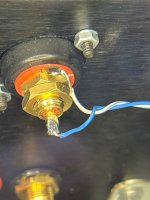
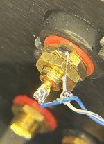
I believe the Audio Gods have smiled on me today. I’m fairly certain I found and fixed the issue with my TDV.
I opened it up and poured over all the visible connections with my magnifying lamp.
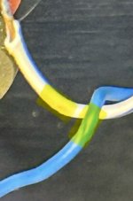
Fired up my soldering iron to touch up the input joints at the RCA connectors and, hello! There you are, you little gremlin.
Just the tiniest nick in the insulation of the input wire to one channel. Both wires. Same spot. So I separated them and put a tiny dollop of cyanoacrylate glue at the offending spot.
Playing well again. Thanks for the well wishes, @ra7!
I opened it up and poured over all the visible connections with my magnifying lamp.
Fired up my soldering iron to touch up the input joints at the RCA connectors and, hello! There you are, you little gremlin.
Just the tiniest nick in the insulation of the input wire to one channel. Both wires. Same spot. So I separated them and put a tiny dollop of cyanoacrylate glue at the offending spot.
Playing well again.
Thanks for the well wishes, @ra7!Attachments
- Home
- Amplifiers
- Pass Labs
- Total Domination VFET (TDV) Amp (using 2SK2087C)