I have been increasing the current on one of the amplifiers.
I am up to 2.9 A with no signs of protest from the amplifier.
There is slightly more heat.
I am using an inverter for my AC and it tells you the power consumed. What is interesting is I would have expected more power to be consumed. My other amplifiers are around 2.55 A. The display shows no increase.
I do not doubt this is not the most accurate gauge but wouldn't one expect to see some change?
One thing I have noticed and this might be the key - when I turn on the amplifier the current is high and continues to settle down over fifteen minutes. I quit monitoring after that so for all I know it may continue downward further still.
If that is the case does this indicate something I have done wrong or some kind of weakness in my implementation? Is it typical for the current to settle downwards over time?
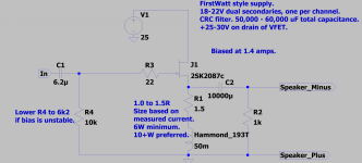
I am using a 400VA transformer - two 15 volts secondaries in series - 40mF, a .1H choke then another 40mF - I would think the power supply should be up to this.
All advice and counsel would be appreciated.
I am up to 2.9 A with no signs of protest from the amplifier.
There is slightly more heat.
I am using an inverter for my AC and it tells you the power consumed. What is interesting is I would have expected more power to be consumed. My other amplifiers are around 2.55 A. The display shows no increase.
I do not doubt this is not the most accurate gauge but wouldn't one expect to see some change?
One thing I have noticed and this might be the key - when I turn on the amplifier the current is high and continues to settle down over fifteen minutes. I quit monitoring after that so for all I know it may continue downward further still.
If that is the case does this indicate something I have done wrong or some kind of weakness in my implementation? Is it typical for the current to settle downwards over time?
I am using a 400VA transformer - two 15 volts secondaries in series - 40mF, a .1H choke then another 40mF - I would think the power supply should be up to this.
All advice and counsel would be appreciated.
Could be the temperature coefficient of the device at play. Also, what choke are you using for the load? You might double-check that its equipped to handle the extra current without saturation.
I am using the Lundahl LL2733 - recommended current 3.4 A. Saturation 5.4 A. It does not get much beyond lukewarm. i think the choke is happy.
Using the same choke in the power supply.
I need to leave the meter connected longer and see if it settles.
Thanks for your interest, Cody. Hope all is well for you.
Using the same choke in the power supply.
I need to leave the meter connected longer and see if it settles.
Thanks for your interest, Cody. Hope all is well for you.

How about this as an explanation:
I am using two different resistors - OHMITE Brown Devils and OHMITE WH in parallel to get to the value I need.
The WNs were recommended by Mr. Yazaki of the SPEC CORP as a good sounding resistor. The BROWN DEVILs were seen in many old tube amplifiers.
I am guessing the two resistors with their different temperature coefficients could be the problem.
Another amp, set to approx 2.7A and using nothing but WHs gets to stability quickly. This amp does not require as low a resistance as the 2.9 A amp.
Only way way to find out. Got some more WHs today and will make a resistor only with those.
Last night the thing did finally settle down after about an hour to just below 2.9 A.
You could also try lowering the value of R1 (R4 in ra7’s original schematic) if the bias is unstable. I went the opposite direction once to see how high I could take it. Wasn’t long before the bias would simply not settle and wanted to run off. That value is going to be different for every SIT, so perhaps the SIT in this specific channel has more gate leakage and requires a slightly lower value? Worth trying if the bias resistor test doesn’t help.
Attachments
Thanks, Cody.
I am in the 7K range already. Does this resistor pass much current?
The current goes down very slowly. One cannot hear anything odd going on. Of course, I would be the biggest liar in DIY audio if I said I can hear the difference between 2.55 A and just shy of 2.9 A! My thinking is this will have more usefulness with the woofer section but the tweeter amps are on top of the woofer amps so the experimentation goes on the amp on top.
The Cobra cable can be heard readily in comparison.
Over the weekend I will assemble the resistor "array" with all OHMITE WHs and see if that makes any difference at all. I can hope.
Take care,
Is your supply up to it? If the transformer sags under load, your power input, which you are measuring, might stay the same. This can happen because we are talking about big current.
Sorry Rick, I think I misunderstood. I was thinking that the channel was seeing a steady increase in bias current.
What happens to the voltage at the supply output when you increase the current?
I am going to find out, ra7.
The inverter is rated for 5000 watts and it says with all four amplifiers on 420 watts is being used which I would think would be a safe margin. The inverter is being supplied by two 200Ah LiFePo batteries and have always been kept charged (charger is turned off when listening). The load is constant with class A amplifiers. Which makes me wonder if the thing doesn't do well with such a constant load? I have my doubts. I did notice that the current through the resistor for the "problem" amp did change when I would turn on additional amplifiers as opposed to where it was powered all by itself. I have no idea how this would be with wall AC power and I that is something else I need to look into. Funny how a problem can alert one to other potential problems. I have not seen whether this occurs with any of the other amplifiers and I know I need to see what happens with them.
Cody, I was wondering if I had not made that clear enough. It is certainly the problem would expect to have instead of this.
Each amplifier is being fed by a 400VA transformer, I would think there would be plenty of current available. Two 15 volts secondaries in parallel. As if I really know how to estimate what the need of the circuit would be.
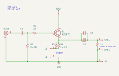
The amps sound great. They must be very forgiving. I figured ra7's approach does allow the amplifier to find its own preferred "place" which is why I decided to go with his circuit notwithstanding I loved the simplicity just as much.
I know this is bordering on arcane wanting to squeeze a little extra power out of the amplifiers but it is something am compelled to try.
Thanks for the help to all of you.
The inverter is rated for 5000 watts and it says with all four amplifiers on 420 watts is being used which I would think would be a safe margin. The inverter is being supplied by two 200Ah LiFePo batteries and have always been kept charged (charger is turned off when listening). The load is constant with class A amplifiers. Which makes me wonder if the thing doesn't do well with such a constant load? I have my doubts. I did notice that the current through the resistor for the "problem" amp did change when I would turn on additional amplifiers as opposed to where it was powered all by itself. I have no idea how this would be with wall AC power and I that is something else I need to look into. Funny how a problem can alert one to other potential problems. I have not seen whether this occurs with any of the other amplifiers and I know I need to see what happens with them.
Cody, I was wondering if I had not made that clear enough. It is certainly the problem would expect to have instead of this.
Each amplifier is being fed by a 400VA transformer, I would think there would be plenty of current available. Two 15 volts secondaries in parallel. As if I really know how to estimate what the need of the circuit would be.
The amps sound great. They must be very forgiving. I figured ra7's approach does allow the amplifier to find its own preferred "place" which is why I decided to go with his circuit notwithstanding I loved the simplicity just as much.
I know this is bordering on arcane wanting to squeeze a little extra power out of the amplifiers but it is something am compelled to try.
Thanks for the help to all of you.
My recent experience with my prototype single ended inductor loaded source follower SiC amp showed different current demands between idling and playing bass heavy music. It was powered by a lab power supply with regulated voltage and current limiting. At idle, the amp was drawing about 2.4 amps but on music peaks, the power supply was hitting its 3 amp limit. This also happened when I was measuring THD at higher power output levels.
Very interesting. I am making these measurements with no music playing.
The amplifier in question is only used from 450 Hz on up so no bass at all even when it is playing.
I made a better resistor bank last night and I think much of my problem has gone away but I am still not sure what is going on.
I am using the DAYTON DATS impedance tester to measure my resistors and I am getting confusing results.
If I test a single resistor it gives results one would expect but when asked to measure 8 resistors in parallel the results have nothing to do with the calculated result from a parallel resistor calculator. This would be eight 5 watts resistors in parallel.
I had built a 250 mA current source to measure the resistances but I worry I have destroyed the LM317 bu turning it on with no load. That is the only thing I can think of that could have ruined it.
When both were working it is interesting how different their results would be. Minor, of course, but one would think there would be some consistency. With the DAYTON DATS you get a different reading every time even with a 5R resistor.
I am starting to think I have gone too low with the resistance and I am going to start again with a higher resistance and work my way back down.
I think the temperature coefficient of the resistors, as you have guessed, whether it is negative or positive would be the main cause of the current differences.
Paralleled resistors, if they have significant inductance will behave differently if in close proximity of each other as the magnetic fields will interact and that would affect the total AC impedance. I would think that a single resistor close to a ferrous object would also measure differently than if it is in a different location.
Paralleled resistors, if they have significant inductance will behave differently if in close proximity of each other as the magnetic fields will interact and that would affect the total AC impedance. I would think that a single resistor close to a ferrous object would also measure differently than if it is in a different location.
Rick,
If you are trying to measure a low resistance with a current using Ohm's Law, a simple method is to use a power supply in conjunction with a power resistor, and connect the low resistance in series with the power resistor. Size the power resistor for approximately the current that you want, and measure the resistance of the power resistor before putting it in the circuit. Then power up and measure the voltage drops across the power resistor and the resistor under test. Use Ohm's Law to determine the current through the power resistor, and use this calculated current to determine the resistance of the resistor under test.
If you are trying to measure a low resistance with a current using Ohm's Law, a simple method is to use a power supply in conjunction with a power resistor, and connect the low resistance in series with the power resistor. Size the power resistor for approximately the current that you want, and measure the resistance of the power resistor before putting it in the circuit. Then power up and measure the voltage drops across the power resistor and the resistor under test. Use Ohm's Law to determine the current through the power resistor, and use this calculated current to determine the resistance of the resistor under test.
An interesting experiment would be to put the paralleled resistors in a series string instead and connect them to a variable power supply. Start with a low voltage (so the resistors stay cool) and measure the voltage drops across each resistor.
Then increase the voltage, let the resistors warm up, and then measure the voltage drops again. It would be interesting to see how the voltage drops change in relation to each other compared to the colder resistors.
Then increase the voltage, let the resistors warm up, and then measure the voltage drops again. It would be interesting to see how the voltage drops change in relation to each other compared to the colder resistors.
Dear Ben - I will try that way. I thought the current source approach would work well and I think it did until something went wrong.
I got the DAYTON DATS to measure loudspeaker parameters and was surprised that it could measure low value resistors so I used that but I am not confident in its accuracy.
I try to measure the LL2733 and the thing tells me it is 85 mH versus the specified 100 mH and a DC resistance of just over 2 Ohms - nowhere close to the specified .85 Ohms. It measures inductance, too. But I wonder about the resistance, I guess it is possible it could be that far off from the specified value but the dcR seems like there is something wrong with the device or there is something wrong with my choke.
I think part of my problem was using much too little resistance - I extrapolated very poorly and kept extrapolating very poorly. Culd I have damaged the choke with my resistances of 0.15R even though they still would only measure 2A?
Could my power supply be anemic? Would that the limiting factor?
The amplifier sounds fine. It seems the B- is where it should be.
Dear ra7 - none of my multimeters are capable of measuring the resistances. They say 1r or 0. I have used different meters to measure the voltage across the resistor and their readings are within expectations.
Unloaded B- - 43.23
With a 0.5487R (? measurement - calculated value 0.5555 so it seems close I measure 1.12 volts across. Just over 2A. Loaded B- 38.59 volts
When I try lower resistance the current seems to remain at 2A.
The other tweeter amp with a 0.5724R is 2.6A. I know this means nothing in THF-51 world. Just thought I would throw it in there.
Any suggestions?
I greatly appreciate the help. Of course, I should have left well enough alone. I figure if you are destroying things you are not learning anything.
In terms of the Dayton DATS measurements of an inductor, it is possible that the capacitance associated with the inductor reduces the level of the AC signal across the inductor and it interprets this as due to the resistance of the inductor. So the result is a lower inductance measurement and a higher resistance value.
A transistor with self bias is kind of a balancing trick since lower source resistance increases current initially, but then Vgs starts increasing (I * R) and also, Vds changes due to current x power supply impedance and the and the source voltage and everything goes round and round until equilibrium is reached. This is definitely not a linear system; simulation with LTspice would be informative.
A transistor with self bias is kind of a balancing trick since lower source resistance increases current initially, but then Vgs starts increasing (I * R) and also, Vds changes due to current x power supply impedance and the and the source voltage and everything goes round and round until equilibrium is reached. This is definitely not a linear system; simulation with LTspice would be informative.
No doubt cheap tools are not definitive. Powered by USB I doubt the DATS has the ability to measure as accurately as they say it can.
After reading your post I measured the capacitance of the inductor in the amp that behaves properly (there is nothing connected to it when I test) and it says 325 uF. If that means anything at all!
This LL2733 gives about the same results as the inductor in the problem amplifier. With this one DATS finds both coils with the same approx 85 mH and in parallel 82 mH with only a slightly lower dcR of 2.4R. Each coil measured 2.5R.
This amp behaves as one would expect with the current rising with lowered resistance.
So there is something peculiar about the "other" amp. The only way I can figure it out is to substitute parts. I do have an extra THF-51 - probably the best place to start.
Thanks,
- Home
- Amplifiers
- Pass Labs
- Total Domination VFET (TDV) Amp (using 2SK2087C)