The measured capacitance of the inductor is quite high and is most certainly inaccurate.
If the bias current is stable and everything is working, another option is to just leave it as is.
If the bias current is stable and everything is working, another option is to just leave it as is.
Rick, Tokin SITs all have a wide range of Vgs versus current. It may be that one of your "problem" THF-51S needs a much lower Vgs to get to a higher current. However since you are generating Vgs with source resistance, as you decrease total resistance, inductor resistance plus resistor resistance, you reach a point of diminishing return as the inductor resistance cannot be lowered.
You can try no source resistor and see what Iq can be achieved. After that, to achieve even lower Iq, you would need a lower DCR inductor or add positive voltage to the THF-51S gate. Or use a THF-51S that has a higher Vgs requirement for a given Iq.
Edit: One question - how low did you go with the source resistor?
Last edited:

Thanks, Ben,
I got down as low as 0.12 calculated but I have not done that again with the bank being made of all the same resistors mainly because when I would go lower than 0.56 (approx. 0.5R) the current stayed the same. The power reading for the inverter would stay at 80 watts. I do suspect I went too low but even with these strange results the amplifier sounded good.
I have wondered if this is the point of diminishing returns with this THF-51. I thought I had seen 2.6 A on this amplifier but I have not seen that since - I could have confused myself which, as you know, is nothing unusual. I am being much more methodical now.
After seeing the DATS results for the choke with the amplifier that behaves properly I do not think the choke is the problem but I am going to disconnect everything and measure it again.
I had mentioned earlier that my motivation for starting this project (which I figure was inspired by Don Quixote) the problem amplifier's power transformer was noisy. Maybe it had always been and I just started noticing it. You can only hear the buzz when standing next to the amplifier. The other three transformers, all purchased at the same time, do not make any noise. I thought if the transformer needs to be replaced why not try a slightly higher voltage one then with the advice I got from you I figured I would just raise the current.
And one thing led to another.
Even at 2 amps the amp does not sound bad. When I measure the tweeters with REW and look at the distortion they are slightly different. The problem amplifier has more 2nd order distortion but not much more. Who knows if this has much meaning? I tend to think the amp with 2.6 A would have less second order distortion.
The fact that lowering the resistor does not raise the current at all, maybe ever so slightly, is what confuses me.
Is it possible the power transformer is broken? I am thinking it is either that or the THF-51 is a funny one.
Just turned the problem amplifier on and i do not hear the transformer buzzing. Maybe i got confused within the timeline and the transformer was buzzing with the really low resistance. I should keep better notes.
Thanks again for your counsel and patience, Ben. You have always been very kind to me and it is greatly appreciated. I know I do not deserve your attention which makes me appreciate it that much more.
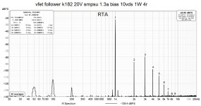
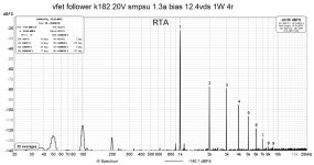
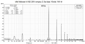
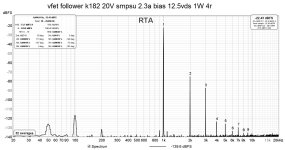
Playing with sits I noticed quite the contrary, you increase the 2nd hd by increasing the bias. If you want to lower it increase the vds of your sitI tend to think the amp with 2.6 A would have less second order distortion.
Rick, the best way to measure current is to measure the voltage drop across a resistance that is in the current path of the amplifier. For instance the choke at the THF-51S source is a good location to measure the current. First get a good measurement of the DCR of the choke. Then use that as the point of voltage measurement to determine current.
To continue scientifically, you can chart the current and resistance and Vgs as you change the resistor value. For each resistor value, measure the current using the voltage drop across the choke. Then calculate Vgs using that current and the sum of the choke DCR and resistor value. This will show you the Vgs and Iq relationship and hopefully show what is happening, rather than guessing what might be happening.
To continue scientifically, you can chart the current and resistance and Vgs as you change the resistor value. For each resistor value, measure the current using the voltage drop across the choke. Then calculate Vgs using that current and the sum of the choke DCR and resistor value. This will show you the Vgs and Iq relationship and hopefully show what is happening, rather than guessing what might be happening.
Ben,
If I could get a good reading of the choke's resistance I would use that. I think the DATS is, now, measuring resistors correctly but I have no faith in its accuracy with the choke so I need to build your apparatus and will.
In the interim I took a current measurement of the current using the DMM with the DMM taking the place of a resistor - with the problem amplifier I get 2.57A and it is stable on the DMM. On the other amplifier I get 3.2 A and this is stable.
Nothing acted funny I guess my resistor bank was bringing about a problem on the problem amplifier. Can't decide whether to add resistance on the other amp or let it remain as is. i think i will listen to resistorless tonight and hear if it makes any sonic difference and whether heat gets out of hand.
With the lower bias amplifier I tried placing the load resistor between the input and before the choke instead of after it and the bias goes to 5A - I left it on long enough to see 5 on the DMM and turned it off immediately.
The amp with 3.2A shows 80 watts power consumption which is what it always seems to show. (using the inverter's power meter and only one amp on) while the problem amplifier with 2.57A draws 100 watts. Hoping you can explain that to me.
Schultzsch, I thought that Mr. Pass said that less 2nd harmonic was what happened when you increase the bias on the SIT 1 amplifiers. Of course, it would not be unusual for me to get it backwards! Thanks for the correction.
And as always THANKS to Ben Mah the mighty audio master tinkerer. (Master tinkerer is something to be proud of. I wish I was one.)
..................
With the lower bias amplifier I tried placing the load resistor between the input and before the choke instead of after it and the bias goes to 5A - I left it on long enough to see 5 on the DMM and turned it off immediately.
The amp with 3.2A shows 80 watts power consumption which is what it always seems to show. (using the inverter's power meter and only one amp on) while the problem amplifier with 2.57A draws 100 watts. Hoping you can explain that to me.
......................
Yes, I like to tinker, but certainly not a master. 🤓
I am not sure what you did. When you said you connected "the load resistor between the input and before the choke", did you connect it to the gate of the SIT to the source of the SIT? If that is what you did then the voltage at the gate was more or less the same as the voltage at the source, or Vgs = 0. No wonder the current maxed out.
Ben,
What have you attempted that you did not master? Seems to me when you decide to do something you do it and with panache.
Rahul had mentioned moving the load resistor from ground to between the resistor and the choke.
Well, I had no problems at all with no resistor between the choke and the SIT. There is no question taking MY resistors out of the circuit made the amps sound better than they ever have. They are quieter than ever - no buzzes.
I have plenty of heatsink - the old DYNACO Stereo 400 heatsink placed upside down so the fan blows through a tunnel of fins.
The 3.2 A side got warmer than it ever has but nowhere near as warm as the SIT 1s did. Of course, there is no easy way to put a fan on those - whether it was important to keep the resistor heatsink cool is something I do not know.

These are not my amplifiers nor my washer and dryer!
Only the heatsink is used and it is upside down with a fan on one end. What little circuit there is is nestled within the rails for mounting the transistors.
I do not think it is my imagination - my resistors were limiting the sonics of the amplifiers. I wonder if any resistor is a problem?
I realized after putting my tools away that if I measure the voltage across the chokes I could get their resistance - or at least I think I have this right? I will do this this evening.
Will be interesting to see what happens with the other two amplifiers. I figure I will place the highest bias current amps on the woofers.
The trick for maximizing the goodness of this amplifier is getting lucky that your choke will not require additional resistance.
Schultzsch, those plots are interesting. I did measure my loudspeakers with REW to see if I could see anything and what I got from the loudspeakers was an evening of the 2nd and 3rd harmonics - second was still dominant but third had risen in comparison to the night before at what was 2 Amps. The 3.2 Amp one had more even distribution than the 2.6 where the 2nd was more dominant. Who knows if this has any bearing?
Thanks very much for the counsel.
What have you attempted that you did not master? Seems to me when you decide to do something you do it and with panache.
Rahul had mentioned moving the load resistor from ground to between the resistor and the choke.
Well, I had no problems at all with no resistor between the choke and the SIT. There is no question taking MY resistors out of the circuit made the amps sound better than they ever have. They are quieter than ever - no buzzes.
I have plenty of heatsink - the old DYNACO Stereo 400 heatsink placed upside down so the fan blows through a tunnel of fins.
The 3.2 A side got warmer than it ever has but nowhere near as warm as the SIT 1s did. Of course, there is no easy way to put a fan on those - whether it was important to keep the resistor heatsink cool is something I do not know.
These are not my amplifiers nor my washer and dryer!
Only the heatsink is used and it is upside down with a fan on one end. What little circuit there is is nestled within the rails for mounting the transistors.
I do not think it is my imagination - my resistors were limiting the sonics of the amplifiers. I wonder if any resistor is a problem?
I realized after putting my tools away that if I measure the voltage across the chokes I could get their resistance - or at least I think I have this right? I will do this this evening.
Will be interesting to see what happens with the other two amplifiers. I figure I will place the highest bias current amps on the woofers.
The trick for maximizing the goodness of this amplifier is getting lucky that your choke will not require additional resistance.
Schultzsch, those plots are interesting. I did measure my loudspeakers with REW to see if I could see anything and what I got from the loudspeakers was an evening of the 2nd and 3rd harmonics - second was still dominant but third had risen in comparison to the night before at what was 2 Amps. The 3.2 Amp one had more even distribution than the 2.6 where the 2nd was more dominant. Who knows if this has any bearing?
Thanks very much for the counsel.
When you raise the bias in your circuit the vds on the sit gets lower(because of the higher voltage drop on the choke) so the 3rd hd increases.
Rick, I don't understand where you moved the resistor then. Is this the schematic of your amp (I know you are using a higher voltage power supply and your source bias resistor may be different)?

Which resistor did you move and where?
If you prefer to not have resistor R1 and find that the current is too high, you can add a negative bias voltage to the SIT gate. You would need an adjustable negative voltage power supply, connect the ground to ground, remove R4's ground connection from ground and connect it to the negative voltage. In tube circuit terms this would be fixed bias. My SIT amps have a bias supply at the SIT gate rather than a source bias resistor.
Yes you can measure the voltage across the choke to determine current if you know the choke's DC resistance.
Your earlier approach of using a CCS to measure should work. A DN2540 et al. based CCS can be set using 47R, say, and then you can insert an additional resistor of small but unknown value and you can measure the voltage across the unknown resistor and find out its value by knowing the current set by the CCS.
Also, I tend not to focus too much on the actual value of the resistor. It is somewhere in the 0.5-2 ohm range because I need a Vgs of -1.0–3.0V and given a current of 2-3A that’s where it needs to be.
I measure the current across the choke, which I measured using the DMM. I recall it came out to 1.1 for both and I am taking its spec’d value, which is 1.0R, as the truth because the DMM ain’t perfect.
The devices have enough spread in the curves that it is not worth trying to match Vgs with any precision. It may be advantageous to keep the resistance in the two channels the same even if the current is a little different.
Last edited:
Rahul,
I cannot remember where the schematic is where you showed an alternate place to connect R4 to get more bias. I thought it was between the choke and resistor instead of ground or in my case B-.
My ears are telling me there is much to be gained by not using the resistor at all.
Changed the fourth amplifier last night to HOT ROD configuration. With no resistor this one is at 2.85 A. Measuring the voltage across the choke tells me the resistance is approx 0.98R - I think this is considerably higher than the specified 0.85R. I will measure the others.
When I find the R of all of the chokes I can (maybe) move them around so that the woofer amps have higher bias than the tweeter amps.
So, I think from what I have heard so far getting the (or more properly MY) resistor out of the way is a sonic revelation. Not that the tonal balance is any different but there is more of what made them good. I completely agree that matching bias current is useless/meaningless. The amps sound released from constraints. Dynamics are DYNAMIC and the soft clipping characteristic is readily heard. VERY rounded clipping. Amps are clipping all of the time, of course, so it is important for the clipping to be unobjectionable. You know it is there but it does not grate on the ear.
I might try a fixed bias scheme but I worry it might spoil the sound I am either really hearing or think I am hearing! I will take a couple of weeks as is and hear what I think.
Back to R4 - can the value of R4 affect the bias current? Mine are around 7K. I am thinking the amp with the 3.2 A bias current which is much higher than the other three - I do not want to add a resistor between the choke and the THF51 - can this resistor be changed to a higher value for a little less bias current?
I cannot stop thinking about how good these things sound without the resistor.
What is wrong with making a simple amplifier even simpler? Nothing I can think of.
As always, my Thanks to Rahul for this amplifier circuit. A large part of the great sound is the SCG line stages driving the amplifiers.
I think an unbypassed source resistor would provide local negative feedback, so that would affect the sound. It would be possible for the resistor to decrease the current as well as distortion.
I must love the sound of distortion! GM, most often in the speakers forums, always says we audiophiles love our distortions.
In my case the added distortion is accompanied by more spatial information and dynamics.
Listened to all four de-resistored last night. Interesting when initially powered up the inverter power meter shows 580 watts (less 60 for the preamps and RYTHMIK amps) being used - after about an half hour this drops to 540 watts (480 for the amps).
Thinking more about the source resistor in an inductor loaded source follower, the resistor does not contribute much to the negative feedback as the inductor's inductive reactance would swamp the effects of the source resistor of a few ohms. I guess it's something else that the resistors are doing to the music.
I could not see how that would be since, as I was told in another thread - a follower is basically 100% feedback so it would be hard to have more than 100%.
I think just getting the resistor out of the circuit is the key. I was using wire wounds - some banks were non-inductive and others inductive wire wounds. I figure getting any element out of a circuit, especially one as simple as this one, makes a difference. In this case I perceive a very good difference. Whether it is the higher current or the lack of the resistor is beyond me but it sure sounded superior.
I will keep it this way for a week or so to hear if I change my mind.
choke in drain must be of exquisite quality
I'm on wrong side of Big Pond, to give you any advice
Zen Mod, would you suggest one in your side of the pond? I have dealt with Ogonowski before and I have heard that this company in the Netherlands can wind good chokes too https://www.aeetransformers.com/products/choke-coils.html (amorphous, etc). Since I will most probably order a custom choke, I would be interested to know (aside from inductance, DCR and current capacity) what core geometry, material, lamination thickness, etc to look for in this application.
Thanks in advance!
Last edited:
- Home
- Amplifiers
- Pass Labs
- Total Domination VFET (TDV) Amp (using 2SK2087C)