post4 estimate is for core area squared.
That applies to all steel cored mains frequency transformers. They can be EI, double E, C, Toroid, R.
That applies to all steel cored mains frequency transformers. They can be EI, double E, C, Toroid, R.
and the others leave with no estimate. One says it all depends on the wire only and the core has nothing to do with maximum power delivery and another says build it, core is not worth calculating.Expect some counter argument.
Last edited:
post4 estimate is for core area squared.
That applies to all steel cored mains frequency transformers. They can be EI, double E, C, Toroid, R.
and the others leave with no estimate. One says it all depends on the wire only and the core has nothing to do with maximum power delivery and another says build it, core is not worth calculating.
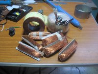
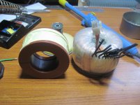
So My core is not more than 100VA. But every page of manufacturer of Toroidal core says Toroidal core is 50% lighter than EI Core with same VA.but My core is 1.84kg. Core manufacturer says 1Kg/100VA core wet required.what's your thought.
Last edited:
Why can't I calculate Maximum VA of core in Toroidal transformer like in EI lamination core I can calculate Final VA by just doing E center leg width*stack height and square the result I get maximum VA of EI lamination core.I wind EI transformer of 14.72cm2 Core area its maximum VA is 216VA and i get secondary out 45/3.7=166VA almost 75% of maximum capacity.
oh yes you can, if only you start building and stop asking...just do it....
So My core is not more than 100VA. But every page of manufacturer of Toroidal core says Toroidal core is 50% lighter than EI Core with same VA.but My core is 1.84kg. Core manufacturer says 1Kg/100VA core wet required.what's your thought.
you worry too much, strop worrying and just do it...
go back and read post4So My core is not more than 100VA. But every page of manufacturer of Toroidal core says Toroidal core is 50% lighter than EI Core with same VA.but My core is 1.84kg. Core manufacturer says 1Kg/100VA core wet required.what's your thought.
Pafi disagrees but has not shown how to design for a particular VA rating.
The generally adopted formulae I gave in post4 give a good estimate.
Pafi has not given any alternative, nor has he shown us how to apply his formula to finding VA.
post5 shows
Toroid steel can generally support a higher flux value and that results in lighter cores.
Using V/Turn = 4.44 * Area * Bmax * Freq gives 4.44 * 0.02m * 0.05m * 1.8T * 50Hz = 0.3996V/Turn or 2.5Turns/Volt for a good steel toroid.
I showed 2 ways and I was waiting for a relevant reply in order to choose, but since no sign of any understanding arrived there was no point in wasting my time.
Once you have the V and turn/V you can choose wire to fit in. It depends on the winding capabilities how much area of the inner hole can be filled with copper, insulator and air, but nobody can tell this except for the person who will make the winding. This is his homework.
Also the user have to determine the operation mode and environment. If somebody refuses to reply anything relevant to these questions then he disqualify himself from learning.
I already wrote VA calculation in an other topic, don't pretend I didn't.
Calculating wire diameter from VA rating is twisted way of thinking. Wire diameter must be choosed according to the space available. (But I'm not going to teach how to wind a coil and basics of geometry here.) Copper cross section for primary:secondary should be about 50:50%. When the diameters are calculated, resistances can be calculated too, and based on this power rating can be calculated also. This way, not backward.
If there is any question about the details, I can help.
Designing for a particular VA is also a waste of time.
as I said in my earlier post MCLYMAN has already worked it all out for ya:
you need the Kg and Ap data from the manufacturer and all the steps are shown in the above pdf file.
you need the Kg and Ap data from the manufacturer and all the steps are shown in the above pdf file.
my rule of dumb for my traffo builds:
1. use 80% of available winding window for copper...
2. of the 80% of available window, 50% each of that for both primary and secondary...
but this is not written in stone, actual builds are different in a lot of ways...
experience teaches you a lot of things not otherwise obtained by mere asking
or reading books or searching the internet...
you got to have lots of actual building experience, only then can you
gain the confidence to move forward....
not by engaging in useless argumentations here...
Power handling capacity-Toroidal core
I found following link.They calculate Maximum power handling capacity of toroidal core.as bellow
VA=5.0*J*Bm*f*Ac min*ID²*10-7
where:
VA =Power handling capacity (VA)
J =Current density (A/ mm2)
Bm =Maximum induction ( Tesla)
f =Frequency ( Hz)
ID =Inside diameter (mm)
Ac min =Effective cross sectional area (mm2)
If I enter My core values in that equation result is as follows.
VA= (5.0*3.1*1.5*50*1000*3600)*0.0000001=418.5
Is that means I can make toroidal transformer up to 418 VA.this website has all information about toroidal core calculation.
EILOR MAGNETIC CORES - Calculation Data
Last edited:
Power handling capacity of magnetic cores is affected by the required regulation, copper space
factor and temperature rise limit. The permissible temperature rise depends upon current density,
flux density, frequency, class of insulation, duty cycle and the heat dissipation capability of the
transformer.
Just like I said.
That figure gives correct result if you achieve the same parameters they calculated with. What are the values? They didnt tell. So all of this is about luck, not real calculation.
are we building a toroid anytime soon?
Yes AJT We meet soon with Toroidal transformer.
https://www.youtube.com/watch?v=Q6GkSNfAEx4
This link is quite interesting and seems worthwhile doing, it could be used as a test type set-up both for HT and sundry heaters.
A couple of questions though:
is he managing to get enough tension on the wires and
not a drop of varnish in sight, is this a safe procedure ?
also would you need to fuse all of the windings as well for safety ?
I think he is definitely not getting enough tension on the wires. It is impossible to do that by hand.
I am not sure whether toroids are normally varnished.
I have a couple but I do not want to rip one open just to find out.
I suspect they're not simply because of the shape.
So if all the windings were fused etc and the thing was fully isolated .. like in a wooden form or something it might still be useable.
It would definitely be a cheap alternative since a similar Hammond power tranny is incredibly expensive for what it is. Close to £160+.
I have opened up a few mains isolation toroids. None were varnished.https://www.youtube.com/watch?v=Q6GkSNfAEx4
This link is quite interesting and seems worthwhile doing, it could be used as a test type set-up both for HT and sundry heaters.
A couple of questions though:
is he managing to get enough tension on the wires and
not a drop of varnish in sight, is this a safe procedure ?
also would you need to fuse all of the windings as well for safety ?
As regards the winding technique:
The wire passing through the middle of the core should be as straight as possible and each turn should be as close as possible to it's neighbour.
At the outer edge the wire tales up about 50% to 60% of the circumference and so each turn should leave a gap of approximately one wire diameter to it's neighbour.
The wire and the insulation should be VERY much TIGHTER, even though he was hand winding. Try hard to really minimise the gaps in the insulation and to pull tight on the turn being wound.
I don't understand what he was doing with the interwinding screen. It looked wrong to me.
The interwinding screen should in my opinion be a complete casing around the whole primary, but with an insulated overlap so that a shorted turn is NOT created. You could with some creative folding do this with one continuous sheet of very thin copper. I suggest it would be much easier to insert a half sheet into the middle of the core and fold it out around the inner edge and turning out over the top and bottom of the primary.
Then wrap an outer sheet that is wide enough to cover the outer height and the top and bottom faces. This can be tack soldered to ONE edge of the first inner copper sheet, to create the complete enclosure. The other edge must not make electrical connection. It must be carefully insulated so that vibration and the secondary tightening does not force the two "open" edges into electrical contact.
External Guass band:
The outer gauss band would be a ring around the outer circumference. It must be made from a permeable material, steel sheet or soft iron sheet or from nickel, mumetal etc. Steel sheet is probably the easiest to find, but quite thin. I suggest a wrap that goes around in at least two whole unbroken turns turns would be better (the example shown had an OD~=200mm. The two turn wrap would need to be ~1260mm long to get a small overlap at the ends. This is insulated and does not get a connection to chassis/enclosure.
Last edited:
toroids have much lower flux leakage than EI's
reason why many use them....
weight to power efficiency is better....
unfortunately, toroids have much higher bandwidth so
the tendency to couple primary noise to secondary coils,
electrostatic shields as shown in the video helps , acting like an antenna
drains noise to ground...
reason why many use them....
weight to power efficiency is better....
unfortunately, toroids have much higher bandwidth so
the tendency to couple primary noise to secondary coils,
electrostatic shields as shown in the video helps , acting like an antenna
drains noise to ground...
Attachments
- Home
- Amplifiers
- Power Supplies
- Toroidal core calculation