Tony,
When you buy wire do you usually buy it as 1 kg blob or do you get larger amounts and break it up into more manageable reels.
It seems the cost can be up to 50-60% less if you get it in larger amounts like 10 kgs.
If you do buy it in larger reels how do you break it down ?
When you buy wire do you usually buy it as 1 kg blob or do you get larger amounts and break it up into more manageable reels.
It seems the cost can be up to 50-60% less if you get it in larger amounts like 10 kgs.
If you do buy it in larger reels how do you break it down ?
one or two kilos....i am not a commercial entity...
i do not mass produce, and many of my amps are a one offs.....
i seldom build the same amp twice that are exactly alike...
i do not even have complete schematics, just bits and pieces written on napkins...
in manila you can buy them in any quantity you like, in 0.1kg increments...
you can even buy them per meter for big diameter wires...😉
going price is about 600 pesos per kilogram....
but the thinner the wire, the higher it costs per kilogram...
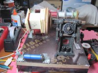
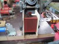
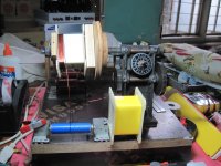
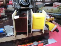
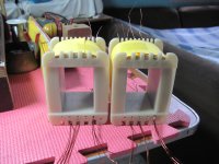
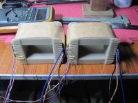
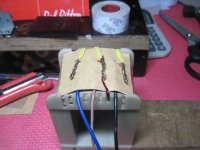
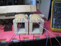
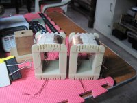
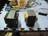
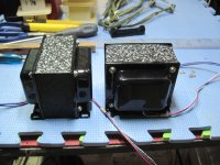
OPT's for a PP 4D32 Class AB2 power amp...
1 1/2 inch center leg stacked to 2.36 inches....
1 1/2 inch center leg stacked to 2.36 inches....
Attachments
-
 IMG_5238.JPG586.6 KB · Views: 394
 -
 IMG_5239.JPG506.7 KB · Views: 383
 -
 IMG_5241.JPG542.3 KB · Views: 345
 -
 IMG_5242.JPG597.5 KB · Views: 338
 -
 IMG_5262.JPG576.3 KB · Views: 195
 -
 IMG_5260.JPG624.2 KB · Views: 198
 -
 IMG_5249.JPG518.6 KB · Views: 233
 -
 IMG_5248.JPG613.6 KB · Views: 275
 -
 IMG_5246.JPG654.9 KB · Views: 260
 -
 IMG_5245.JPG577.1 KB · Views: 329
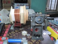
hi, i bought 5 old transformers and i dismantled one, its 3.8 cm center leg 5 cm stack with primary winding around 260 turns and secondary around 44 turns. i wanted to make a power supply for my new project. how much ampere can i get from stacking them together? i also wanted to know the no. of turns in primary and secondary and gauge wire to use.
here are my details:
220 volt primary and secondary 50 volt center tap
here are my details:
220 volt primary and secondary 50 volt center tap
hi, i bought 5 old transformers and i dismantled one, its 3.8 cm center leg 5 cm stack with primary winding around 260 turns and secondary around 44 turns. i wanted to make a power supply for my new project. how much ampere can i get from stacking them together? i also wanted to know the no. of turns in primary and secondary and gauge wire to use.
here are my details:
220 volt primary and secondary 50 volt center tap
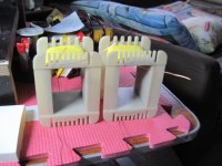
looked like those are 1.5 in center leg, stacked to 2 inches, good for about 280VA each.....
if running at 220 volts, idle current is on the high side, can you confirm idle current?
and at 220 volt input output is about 37 volts, not far off your intended voltage...
if you can tell me what amplifier you are trying to build, i can give you further advise....
btw, it is cold there in saudi now right?
Nice pics sir...
Btw, for power traffo how do you reduce noice and increase its efficiency?
It may not be big issue in actual but it can make good quality traffo.
Btw, for power traffo how do you reduce noice and increase its efficiency?
It may not be big issue in actual but it can make good quality traffo.
Nice pics sir...
Btw, for power traffo how do you reduce noice and increase its efficiency?
It may not be big issue in actual but it can make good quality traffo.
use of M6 instead of the M50 deeco irons is a good way,
M18 is also good middle ground, better than M50..
an electrostatic shield made from copper foil strips between primary
and secondary coils is another good step, just be careful not to short that winding,
once around is okay, with a pigtail that you can connect to psu ground...
If you reduce the flux to around 0.7T it turns out to be around 200VA for 1.5" * 2" core.hi, i bought 5 old transformers and i dismantled one, its 3.8 cm center leg 5 cm stack with primary winding around 260 turns and secondary around 44 turns. i wanted to make a power supply for my new project. how much ampere can i get from stacking them together? i also wanted to know the no. of turns in primary and secondary and gauge wire to use.
here are my details:
220 volt primary and secondary 50 volt center tap
VA = 31 * core area² when flux = 1T.
adjust the flux to suit the transformer type and material.
If you stacked the laminations to around 3" to make a 1.5" * 3" core you can get the transformer VA up to around 400VA for the same 0.7T flux.
looked like those are 1.5 in center leg, stacked to 2 inches, good for about 280VA each.....
if running at 220 volts, idle current is on the high side, can you confirm idle current?
and at 220 volt input output is about 37 volts, not far off your intended voltage...
if you can tell me what amplifier you are trying to build, i can give you further advise....
btw, it is cold there in saudi now right?
Hi, tony thanks for the quick reply. Yup its fairly cold down here. 22 degree C. 😀
Now i have a problem in measuring the transformers, my friend was too excited dismantling all fours, coz i promised him to give him all the copper wires and i only want are the cores and bobbins.
my new project will be apexaudio's B500
here in my place (jeddah) i have no problem buying the copper wires. But difficult to buy new cores. 😕
If you reduce the flux to around 0.7T it turns out to be around 200VA for 1.5" * 2" core.
VA = 31 * core area² when flux = 1T.
adjust the flux to suit the transformer type and material.
If you stacked the laminations to around 3" to make a 1.5" * 3" core you can get the transformer VA up to around 400VA for the same 0.7T flux.
thanks for the reply Sir Andrew,
Hi, tony thanks for the quick reply. Yup its fairly cold down here. 22 degree C. 😀
Now i have a problem in measuring the transformers, my friend was too excited dismantling all fours, coz i promised him to give him all the copper wires and i only want are the cores and bobbins.
my new project will be apexaudio's B500
here in my place (jeddah) i have no problem buying the copper wires. But difficult to buy new cores. 😕
can you post a picture of the lams? and what is the thickness? if its 0.5mm, chances are it can be M50, if 0.35mm it could be something better...
if you can order stuff from the states, i suggest that you look here....http://www.alphacoredirect.com/contents/en-us/d3_toroidal_cores.html and http://www.alphacoredirect.com/contents/en-us/d1_goss_ccores.html
this is a very good site for learning to make torroids, although the language is spanish, yet is easy to understand..
https://www.youtube.com/watch?v=Q6GkSNfAEx4
at this point i will discourage surpluss mentality, let us learn to make new things instead.
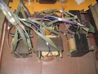
the shape of things to come....two rows on the left are OPT's, the rest are power traffos and chokes for upcoming projects...
a pair for a 4D32 single ended amp, the rest are for push-pull amps..
a pair for a 4D32 single ended amp, the rest are for push-pull amps..
An externally hosted image should be here but it was not working when we last tested it.
wow, lorra lorra metal !
I have now picked up all the small metal parts to build a winder and I also acquired eight cores from Eilor in Israel in january [thankfully before the Euro went belly-up] but I noticed when I bought them that generic c-cores have quite a small area of metal to work with. Pat Turner alludes to this fact also.
I have two standard Lundahl trannies [rated for 160 watts p-p according to Lundahl] and although 30% lighter than the Eilor cores [2.2kg] the Lundahl leg area is about the same as the Eilor cores I purchased, about 10 square cms. Maybe Lundahl wind their own cores. I have to say compared to Pat Turner's transformers 10 cm square seems seriously small.
So if ever I actually get around to building a transformer before I die my problem is I will have to use many more turns than I would if using lams.
The material I purchased was M4 grade so not sure what tesla value I can plan to operate them at, but certainly higher than M6 lams so that will help slightly ?
More turns means more inductance which is good, right ?
Is there a limit to how much inductance it is appropriate to use ? Can you plan for too much inductance ?
What I basically trying to do is match/equal the impedance from the plates to impedance/equivalent inductance on the primary, correct ? This matter is confusing.
The c-cores have a much greater window area than equivalent lams so I can fit the extra wire in but which would be better in terms of capacitance ?
Lams may mean more vertical layers than c-cores but the width of the layers in the c-cores would be greater since c-cores are quite tall.
Does capacitance simply depend on overall area or is there a question of series v parallel capacitance in the windings of a transformer ?
Capacitance adds in parallel but divides in series so how is this resolved ?
Leakage inductance in the c-cores should be smaller though ?
Pound for pound the cores are better than lams at producing power but the real problem is I would have to use lower voltages using c-cores as I still don't want to have to use too many turns .. so that may involve having to parallel tubes etc .
Many of these questions are rhetorical AJT so don't feel under any pressure to answer them 🙂
M4 is a better grade of lams than M6, M18 and M50...
the lower the number after the M the better...
all else being equal, you can get more inductance with M4...
or same inductance with fewer turns..
then thickness of lamination, 0.35 is better than 0.5 mm in terms of eddy current loss...
the purpose of this thread is to catalog and document traffos that i have done,
not so much to dwell in theories as with practical working examples...
all such information are freely available elsewhere,
and i do not want to discuss what another has done before,
just to apply them in my builds as i understood them...
while there are those who would like to talk and talk yet do nothing,
i would like to build based on what i learned, and the resulting products
will reveal if indeed i learned anything at all...
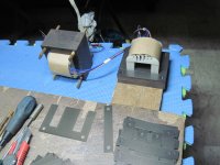
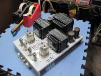
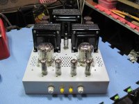
my DIY power traffos for SS amps...the one on the left is good for 200 watt per channel, the one on the right is good for 100 watt per channel....
this is a modularised, psu for my second honeybadger, the soft starter, the speaker protector delay boards
will sit in this subchassis, hopefully i can test my badgers even before a chassis is built...
An externally hosted image should be here but it was not working when we last tested it.
An externally hosted image should be here but it was not working when we last tested it.
this is a modularised, psu for my second honeybadger, the soft starter, the speaker protector delay boards
will sit in this subchassis, hopefully i can test my badgers even before a chassis is built...
An externally hosted image should be here but it was not working when we last tested it.
i made a filament traffo for a friend who wanted to build a Tabor clone amp by Gary Pimm..
An externally hosted image should be here but it was not working when we last tested it.
An externally hosted image should be here but it was not working when we last tested it.
An externally hosted image should be here but it was not working when we last tested it.
- Home
- Amplifiers
- Power Supplies
- Tony's latest traffo DIY build