Not too familiar with if this chip can handle parallel operation, if you have seen any other implementaions that follow that route, I gues you can copy the important bits, and maybe keep the filters from this design.
Recommended Supply 2x18VAC or a centretapped 36V transformer of at least 80VA.
Rails must not exceed 30VDC.
Supposedly good for 20W.
Recommended Supply 2x18VAC or a centretapped 36V transformer of at least 80VA.
Rails must not exceed 30VDC.
Supposedly good for 20W.
What happens if the rails exceed 30+30vdc?
Does it shut off, or do you just thermal glue another heatsink to the one you already have?
20W? Well, they can do more (understatement). Try my design on some 4 ohm speakers and be prepared for a surprise. 😉
Does it shut off, or do you just thermal glue another heatsink to the one you already have?
20W? Well, they can do more (understatement). Try my design on some 4 ohm speakers and be prepared for a surprise. 😉
Hi Daniel,
finally !!!! You have the bandwidth defined by the input filters. You took your time getting there.
When the NFB cap rolls off the bass you find that excessive AC voltage appears on the NFB cap and I suspect that is what you describe as chipamp colouration. It is not the chipamp. It is inappropriate design decisions (that's a polite way of saying pig headed intransigence).
Now, go back and adjust the RC time constants as I suggested way back. Aim for 80 to 90mS and 0.5 to 1uS at the input and ensure that all the bandwidth adjustments inside the amplifier are wider than the input filters you choose.
AndrewT said:Hi Daniel,
finally !!!! You have the bandwidth defined by the input filters. You took your time getting there.
When the NFB cap rolls off the bass you find that excessive AC voltage appears on the NFB cap and I suspect that is what you describe as chipamp colouration. It is not the chipamp. It is inappropriate design decisions (that's a polite way of saying pig headed intransigence).
Now, go back and adjust the RC time constants as I suggested way back. Aim for 80 to 90mS and 0.5 to 1uS at the input and ensure that all the bandwidth adjustments inside the amplifier are wider than the input filters you choose.
I had to cheat with the input filters. The nearest single cap that I could get to work was 0.068uf. However, tandem (parallel) pair of polyester 0.022uf (0.047uf total) set up bucking/opposition (face to face), did finally work.
EDIT: Its not that I didn't believe you, its that I wanted to prove it. The gain is also a source of coloration. I had to do the cheat (above) to get the clean power above 80 watts and still avoid the coloration. --several possible sources of coloration.
Thanks for the efficiency boost!!
Can you clarify what changes you'd like to see on the most recent chart?
Hi Daniel,
I suggest you move towards increasing the input cap from 0.047uF to ~1uF.
similarly increase 22uF to ~60uF and 1r0 towards 4r0.
But, remember the most important rule is that the input filters define the bandwidth.
You should then find that gain and NFB values will have much less effect on the colouration.
AndrewT said:Hi Daniel,
I suggest you move towards increasing the input cap from 0.047uF to ~1uF.
similarly increase 22uF to ~60uF and 1r0 towards 4r0.
But, remember the most important rule is that the input filters define the bandwidth.
You should then find that gain and NFB values will have much less effect on the colouration.
On LM1875 pictured, I had wanted flat response till 43 hz and then minus 3 db somewhere around 30hz. So, of course I could crank the NFB gain along with the efficiency in an attempt to break plaster with hi-fi, and succeed. 😉 Great fun!! Thanks man!!
So, what remains for it is to change the zobel resistor from 1R up to something higher? OH!! Of course, its a polypro cap, which is a capactive load (1ESR + 1R = 2 ohm load), and so you're saying to make it a 5 ohm capacitive load instead?
Is that right?
National say 2r7 and I can't recall anyone saying it does not work. But I think that value is quite low for an output stage that cannot source much current. That's why I'm suggesting upto 4r0 but at least more than 1r0.change the zobel resistor from 1R up to something higher?
Yes! I understand that as the same as guidelines for a piezo tweeter.
Thanks for pointing it out. 😉
I would like to keep the same frequency response for the zobel because I sure do enjoy the way this amplifier sounds.
Do you think that the cap value must change along with the resistor value for this?
Thanks for pointing it out. 😉
I would like to keep the same frequency response for the zobel because I sure do enjoy the way this amplifier sounds.
Do you think that the cap value must change along with the resistor value for this?
Oh, say, do you think that LM3875 has a similar fidelity to LM1875?
I ask because I own some LM3886 kits and (edit, edit, rant deleted), I'm hoping to repair that issue. 😉
I ask because I own some LM3886 kits and (edit, edit, rant deleted), I'm hoping to repair that issue. 😉

Speaker zobel
So, that above was very loud treble, and not where its most pleasant.
I tried varying resistor values, but except for the K50's factory specs (0.22uf polypro and 1 ohm), there was a problem.
Okay, so I tried 0.68uf mylar and 1 ohm. That's less load than polypropylene. It had the effect of a rather boring sound and all the brass instruments weren't represented right.
I tried 0.22uf polyester and got a similar effect to the factory layout, except that the effective pitch was too low. Nice clue!
The simplest solution. . .
So, I tried 0.1uf polyester, leaving the factory 1 ohm resistor in place, a very light load indeed, and it's got more "air" slightly more forwards, but yet very, very nice. Tripath hits the bin. More air! Lighter load! Nice bargain. 😉
Andrew, thanks for the clues!
Here it is. For me, its like getting brand new ears. 😉 This does what I want from an amp, so now how do I drive a FET with it?
Attachments
Dang!
Showing an unlevel frequency response now. A bit of screech on some popular music as well as less compatible with reverb because its making the chip get really hot!
I guess that the makers of K50 decided on a speaker output zobel of 1 ohm and 0.22uf mini polypropylene. . . for a very good reason. It sounds good. Well, I tried the options. 😉
Its nice on the widest varity of sources this way:
Attachments
Hi there
Having started this thread off it was great to come back to it after all this time and find out how things have progressed, lots of really interesting ideas at the opposite end of the spectrum to my attempts, anyhow I thought an update might be in order.
I have now been running my microclones for a good while and the sound has continued to amaze in my high efficiency wide range application. I am about to build a pair of bridged LM1875s running on 16 volts battery supplies and I'm pretty confident the sound will be very nice, these will be microclones like the others and built with a combination of point to point smds and regular parts on a ground plane.
I think I will try a couple of the ideas here as well on a separate amp, well it is cheap as chips to try isn't it.
Just one thing, everyone here seems to be running AC based supplies, I can't emphasise enough just how much better an LM1875 sounds on battery power, I challenge some intrepid tweaker working here on this new circuit to substitute the power supply with batteries, say +/- 24v or maybe 36 if your really game and have enough SLAs and just see how it sounds......to my mind it really is worth the hassle. You could go 30V but you would need 5 6v cells per rail! Actually 2 12v SLAs is about 26v fully charged so close enough to 30 anyway.
I would love to hear some feedback after this.
I have recently been wondering if there might be further improvements by using batches of plain old heavy duty D Cells, there is one very expensive commercial amp that uses such an arrangement and it gets utter rave reviews (it is based on a chip amp, though not this one). You would think it might go through heaps of cells however if you are running very efficient speakers the life is apparently quite good and I can buy D cells for less than 80 cents each so in the scheme of things it might not be as exy as it first appears. Anyhow out of curiosity I am prepared to give it a go, if it doesn't sound better then I will use the cells in torches.
Back in my original post I mentioned how important I felt the pre-amp was, since then I have only had that idea reinforced by experience, small changes to the pre-amp are always telescoped through the gainclones and seem to have a large effect of depth/soundstage, high end clarity etc. In fact the difference in sound between running the pre on battery power and AC is quite amazing, even with the clone on batteries. In the end I think the microclone or any well built LM1875 based amp is ultra revealing and basically works pretty much like the "straight wire with gain" so it needs to be really well fed.
I guess the thing that really strikes me once running on full battery power is just the utter lack of grain, it just sounds so smooth.
The great thing is that there are just so many ways to build these things and it is relatively easy to match the method to ones system and needs, overall I think it is synergy that counts most.
To ZeroOne
Took your advice.
Run my 2 mono LM1875's on 2 sla's'.
Sound is terrific!!
Thanks alot ZERO ONE !!
I also use a tube pre-amp (TPR 1), very cheap, wich improved the sound even more!!
My large open baffle's don't need more power!!
I'm looking for a decent on/off switching device for the sla's...
any good tips around??
Questions for Nordic

Okay. I do have a question or two, though.
In order to make A-B comparisons using the same source equipment, C8 (input filter cap) goes random unless R1 (input in-series) is between it and the source.
Its not necessary to move R1 though because an additional resistor could just be added between capacitor and source.
I need to protect that capacitor against external effects before I can successful A-B test the amplifier.
How would you like to proceed there?
There are many who would like a potentiometer at X1. I'd like to simulate it during testing with an equivilent load. Should this additional load at the input be 22k, 50k, 100k, or 250k?
On R2, the input will overdrive before reaching 8 steady watts if the source hasn't already overdriven itself. Not everyone owns Lowthers. A lower value is needed for R2, before a comparison can be made. My best guess is 470 ohms, which should give about 34 steady watts output into 8 ohm speakers (with music transients at several times). Is this okay?
That's what would make the project interesting to me.
However, this conflicts so that C7 needs to be 100uf if C8 is 1uf so that the NFB isn't corrupted by a bandwidth limitation that makes a sound.
OR, if C7 is left at 22uf, then the input filter cap would be 0.22uf, which might be more appropriate for such a small amplifier.
Which would you prefer?
Nordic said:OK now try the one I posted.. you allready have all the parts...
Okay. I do have a question or two, though.
In order to make A-B comparisons using the same source equipment, C8 (input filter cap) goes random unless R1 (input in-series) is between it and the source.
Its not necessary to move R1 though because an additional resistor could just be added between capacitor and source.
I need to protect that capacitor against external effects before I can successful A-B test the amplifier.
How would you like to proceed there?
There are many who would like a potentiometer at X1. I'd like to simulate it during testing with an equivilent load. Should this additional load at the input be 22k, 50k, 100k, or 250k?
On R2, the input will overdrive before reaching 8 steady watts if the source hasn't already overdriven itself. Not everyone owns Lowthers. A lower value is needed for R2, before a comparison can be made. My best guess is 470 ohms, which should give about 34 steady watts output into 8 ohm speakers (with music transients at several times). Is this okay?
That's what would make the project interesting to me.
However, this conflicts so that C7 needs to be 100uf if C8 is 1uf so that the NFB isn't corrupted by a bandwidth limitation that makes a sound.
OR, if C7 is left at 22uf, then the input filter cap would be 0.22uf, which might be more appropriate for such a small amplifier.
Which would you prefer?
To Zero One
I do have some feedback on A/C power vs. sound.
Using stock K50 lm1875 as a baseline, here's something odd:
28v center tap transformer (and lower voltages) make a rather dark and masked presentation--smooth, but masked.
36v center tap transformer (and higher voltages) make a bright and analytical presentation--clear, with a slight grain.
Oddly enough, the LM1875 is so efficient that only 36va is used (so 36vct is $12 transformer).
Does these observations provide any helpful correlations to your research on various batteries?
Since I believe in "accessable" projects, but don't really want to sacrafice quality for quantity, could we perhaps make a battery system pay for itself via solar power?
There's also a reference in old op-amp documents that a resistor at the output decreases the heat, so I wonder if a 1R (or so) Mills will make the batteries last twice as long, because it does drop the heat at the heatsink on my test bench?
Zero One said:Just one thing, everyone here seems to be running AC based supplies, I can't emphasise enough just how much better an LM1875 sounds on battery power, I challenge some intrepid tweaker working here on this new circuit to substitute the power supply with batteries, say +/- 24v or maybe 36 if your really game and have enough SLAs and just see how it sounds......to my mind it really is worth the hassle. You could go 30V but you would need 5 6v cells per rail! Actually 2 12v SLAs is about 26v fully charged so close enough to 30 anyway.
I would love to hear some feedback after this.
I do have some feedback on A/C power vs. sound.
Using stock K50 lm1875 as a baseline, here's something odd:
28v center tap transformer (and lower voltages) make a rather dark and masked presentation--smooth, but masked.
36v center tap transformer (and higher voltages) make a bright and analytical presentation--clear, with a slight grain.
Oddly enough, the LM1875 is so efficient that only 36va is used (so 36vct is $12 transformer).
Does these observations provide any helpful correlations to your research on various batteries?
Since I believe in "accessable" projects, but don't really want to sacrafice quality for quantity, could we perhaps make a battery system pay for itself via solar power?
There's also a reference in old op-amp documents that a resistor at the output decreases the heat, so I wonder if a 1R (or so) Mills will make the batteries last twice as long, because it does drop the heat at the heatsink on my test bench?
To Nordic
To Nordic:
My apologies! I made an error. Here it is:
"OR, if C7 is left at 22uf, then the input filter cap would be 0.22uf, which might be. . ." wrong. Sorry.
That, at the same gain, would make the shunting part of the NFB to 470R, and large DC offset. I apologise again! I had failed to check the National spreadsheet against empiric data.
The 1k is fine, but I need more gain--much more.
The "OR" suggestion should have been a lot of values of 47's and 1's. Its like this: NFB 47k, 1k, 47uf. Input 47k, 1k And, the 1k Rb (or another piece) positioned to protect the input filter cap away from the source--with that input filter cap, perhaps a tandem pair of 0.1uf (x2 = 0.22uf) for a flat response to 25 hz, with "down by 3db" at 15 hz. 😉
That's also the gain that I need, one of the possible combinations for good hi-fi with good power, and I'd sure like to know what the rest of the design looks like in a "47k with 1k" layout or the (far above) "100k with 2.2k" layout (your choice, of course).
Thank you!!
You are trying to drive the chip outside of its know good parameters...
Firstly this chip is rated and marketed as a 20W chip, although National does admit it will reach over 30W on supplies up to 30W.
One has to ask yourself, at what cost to linearity and distortion...
What happens when the internal 4A current limit is hit? Or the SOA protection is activated? All of this without getting the thermal protection to jump in there and shut the amp down (at about 170C).
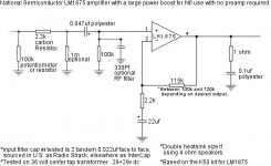
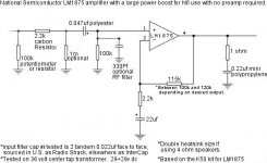
The closed loop gain set to 23 by the 22k (R3) and 1k resistor on the inverting input.
I.e. voltage gain = 23... ever thought what happens if voltage gain dictates to amp that it has to go higher than the supply rails?
The 22uf in series with 1k sets the lower end of the frequency response, and another factor is the 2.2uf cap and the 22k (R4) forming a high pass filter.
The result is a rapid frequency response roll-off below about 10Hz.
Following this is a 1k resistor and 330p cap to form a low-pass filter.
"In order to make A-B comparisons using the same source equipment, C8 (input filter cap) goes random unless R1 (input in-series) is between it and the source.
Its not necessary to move R1 though because an additional resistor could just be added between capacitor and source.
I need to protect that capacitor against external effects before I can successful A-B test the amplifier.
How would you like to proceed there?
"
I do not get what you are trying to say. C8 and R4 acts as a filter.
On R2, the input will overdrive before reaching 8 steady watts if the source hasn't already overdriven itself.
Huh? the source is driveing a 1M load... is it powered off the falpping of butterfly wings?
R2 is simply forming the gain ratio as a simple resistor voltage diver in combination with R3.
Voltage over R2 = 1 23rd of voltage on output.
Voltage on pin 1 should equal pin 2 and so the feedback forms a control loop by trying to mimic the input on pin1.
Why keep the amp under 20W?
Because THD rises like a brick wall form the ground, just east of 20kHz.
measurements given are often not maximums, but conventional ways of comparing things. For instance the amp at 1W into 8 ohm, is virtualy flat in response from about 15Hz to just shy of 100k.
Go and try it, it would take less time to breadboard that circuit than it took you to type your worries....
That crystal clearness you think you are hearing is distortion...
Firstly this chip is rated and marketed as a 20W chip, although National does admit it will reach over 30W on supplies up to 30W.
One has to ask yourself, at what cost to linearity and distortion...
What happens when the internal 4A current limit is hit? Or the SOA protection is activated? All of this without getting the thermal protection to jump in there and shut the amp down (at about 170C).
The closed loop gain set to 23 by the 22k (R3) and 1k resistor on the inverting input.
I.e. voltage gain = 23... ever thought what happens if voltage gain dictates to amp that it has to go higher than the supply rails?
The 22uf in series with 1k sets the lower end of the frequency response, and another factor is the 2.2uf cap and the 22k (R4) forming a high pass filter.
The result is a rapid frequency response roll-off below about 10Hz.
Following this is a 1k resistor and 330p cap to form a low-pass filter.
"In order to make A-B comparisons using the same source equipment, C8 (input filter cap) goes random unless R1 (input in-series) is between it and the source.
Its not necessary to move R1 though because an additional resistor could just be added between capacitor and source.
I need to protect that capacitor against external effects before I can successful A-B test the amplifier.
How would you like to proceed there?
"
I do not get what you are trying to say. C8 and R4 acts as a filter.
On R2, the input will overdrive before reaching 8 steady watts if the source hasn't already overdriven itself.
Huh? the source is driveing a 1M load... is it powered off the falpping of butterfly wings?
R2 is simply forming the gain ratio as a simple resistor voltage diver in combination with R3.
Voltage over R2 = 1 23rd of voltage on output.
Voltage on pin 1 should equal pin 2 and so the feedback forms a control loop by trying to mimic the input on pin1.
Why keep the amp under 20W?
Because THD rises like a brick wall form the ground, just east of 20kHz.
measurements given are often not maximums, but conventional ways of comparing things. For instance the amp at 1W into 8 ohm, is virtualy flat in response from about 15Hz to just shy of 100k.
Go and try it, it would take less time to breadboard that circuit than it took you to type your worries....
That crystal clearness you think you are hearing is distortion...
My apologies. I was unclear.
My source is Soundblaster X-Fi, although I do have a battery CD player handy.
The power at my location has the effect of a large noise on other sources, including randomly exploding RIIA amps (a very large noise indeed!). There is also a small matter of a metal clad building plus interference that its supposed to block, but instead, it increases. Located atop the highest hill, lightening strike is frequent.
One thing that troubles my source of choice is a large DC output. Another thing that troubles it is a rather weak output of audio.
I have listened extensively to my lm1875 amplifier on that source, so I would like to use the same source during comparisons of amplifiers.
I hope that helps bring clarity to some of my comments.
With this:
Thank you for the elegant design. I really like it.
It seems that I'm missing some necessary support equipment that would let me enjoy it.
I have neither a powerful source nor a reliable electrical outlet to power it.
I have neither hyper-efficient speakers, nor the funds for those I would like.
Again, I apologise for the situation and for being unclear as to why I needed the gain.
That does also make a nice increase in dynamics. 😉
Thanks again!
My source is Soundblaster X-Fi, although I do have a battery CD player handy.
The power at my location has the effect of a large noise on other sources, including randomly exploding RIIA amps (a very large noise indeed!). There is also a small matter of a metal clad building plus interference that its supposed to block, but instead, it increases. Located atop the highest hill, lightening strike is frequent.
One thing that troubles my source of choice is a large DC output. Another thing that troubles it is a rather weak output of audio.
I have listened extensively to my lm1875 amplifier on that source, so I would like to use the same source during comparisons of amplifiers.
I hope that helps bring clarity to some of my comments.
With this:
Yes. That makes a sound almost as bad as a factory spec LM3886. 😉 I intend to make this sound *only* during the loudest of transients, which is a fantastic substitute for clipping.One has to ask yourself, at what cost to linearity and distortion...
What happens when the internal 4A current limit is hit? Or the SOA protection is activated? All of this without getting the thermal protection to jump in there and shut the amp down (at about 170C).
Thank you for the elegant design. I really like it.
It seems that I'm missing some necessary support equipment that would let me enjoy it.
I have neither a powerful source nor a reliable electrical outlet to power it.
I have neither hyper-efficient speakers, nor the funds for those I would like.
Again, I apologise for the situation and for being unclear as to why I needed the gain.
That does also make a nice increase in dynamics. 😉
Thanks again!
- Home
- Amplifiers
- Chip Amps
- Thoughts On LM1875 Gainclones