Wow. That's great stuff. Thank you!
So the chart had no errors except the volume control pictured at maximum? My goodness! I might be learning. 😉
Does the 330Picofared go before or after the 50k?
How do I make a stereo differential input using only capacitors and resistors? lol! That's a heck of a question, isn't it?
For reference, here's a mono differential input, also called Hafler rear channel.
A pair of 100k loads at the end of a stereo signal cable.
A pair of capacitors in series with the + for left and right.
They are the only input for a monophonic amplifier (the ground does not connect).
I need two of these, except that I need one to favor right side information and the other to favor left side information. . . as simply and easily as possible. 😉 Either that, or I need a remarkably easy stereo expander (it might sound similar).
danielwritesbac said:Wow. That's great stuff. Thank you!
So the chart had no errors except the volume control pictured at maximum? My goodness! I might be learning. 😉
Does the 330Picofared go before or after the 50k?
How do I make a stereo differential input using only capacitors and resistors? lol! That's a heck of a question, isn't it?
For reference, here's a mono differential input, also called Hafler rear channel.
A pair of 100k loads at the end of a stereo signal cable.
A pair of capacitors in series with the + for left and right.
They are the only input for a monophonic amplifier (the ground does not connect).
I need two of these, except that I need one to favor right side information and the other to favor left side information. . . as simply and easily as possible. 😉 Either that, or I need a remarkably easy stereo expander (it might sound similar).
Hi Daniel,
You're welcome.
I wouldn't say that those are the ONLY things that I would consider, for your schematic. They're just what I happened to mention, off the top of my head, so to speak. And there are others here who are much more knowledgable than I.
Just as an example, there are probably conflicting reasons for choosing the magnitudes of the values of the resistances in the feedback loop. One consideration is that larger resistances generate more noise (Even an unpowered, unconnected resistor generates its own noise voltage, with magnitude proportional to its resistance (and temperature)). However, if you go TOO low for the resistance values, you might run into non-linearities, possibly even, for example, due to self-heating changing a resistance as a function of the voltage across it, which would definitely not be a good thing. For that reason, it might also be wise to use higher-wattage-rated resistors, there, even if it appears to be "unnecessary" if considering only the average power dissipations.
But, as with many, many such considerations, unless we really know what kinds of magnitudes all of the effects have, we don't really know whether or not they might be significant-enough to even worry about. Nevertheless, I usually opt for the lowest "reasonable" resistances, just to minimize the noise, all else being equal. You could probably safely set the lower gain-setting/feedback resistance to somewhere between 0.5k and 1k, and then scale the other one down, proportionately, unless there are other reasons that you want them to be large (which I vaguely feel you might have mentioned, but can't quite remember). There are probably also other considerations, possibly much more significant, that I'm not mentioning, maybe having to do with offset and bias voltages and currents of the chipamp, and matching the impedances seen by the two input pins, for example, and maybe also the effect on the impedance seen by the output pin. Others, here, will probably be better-able to comment on what is most important, there. However, it might also be relatively easy to just "experiment".
You also haven't shown the power supply decoupling circuitry. That is often just a large cap and a small cap in parallel, from each power supply pin to ground. Also note that the "power" and "audio" ground returns, at the least, should be completely separate, all the way back to the power supply, or to your "star ground" point, so that voltages induced back at the amplifier end of the ground return conductors, by ground-return currents flowing through the conductors' impedances (V = I x R _plus_ V = L x di/dt), are not forced onto low-level circuits' ground-reference points, causing a changing ground voltage, which effectively would arithmetically sum with the signals that are referenced to those points, for example (i.e. "not a good thing").
You will also want to try to keep all power and signal conductor PAIRS as close together as possible, to minimize their enclosed geometric "loop areas", which minimizes both incoming and outgoing electromagnetic interference effects, for each current loop (see "Faraday's Law", or applications of "Maxwell's Equations"). For point-to-point wire pairs (for both signals and power), you would also want to twist them tightly together.
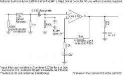
Regarding the 330 pF cap: I usually try to put the RF filter JUST before the input pin (basically because RF wavelengths can be very, VERY short, and I want to minimize the "antenna" length absolutely as much as possible). But I think that you would need to add a 2.2k series R just before the 330 pF, to form an RC lowpass filter with the cap. And even better way might be to use two series resistors, there, with the cap to ground from _between_ them, for bi-directional filtering (which is also the _required_ method, if putting an RF filter before a NEGATIVE chipamp or opamp input, since a capacitance to ground would need to be isolated from a negative input, to prevent oscillation).
I'm not sure what you mean, about the "stereo differential input". Typically, one would use one amplifier for each of the two stereo channels. Or are you trying to convert stereo to mono? If so, you could use a simple one-opamp "summing amplifier" (See, for example, AN-31 and AN-20, at http://www.national.com .) Otherwise, you could use a passive summing circuit, basically two large-ish resistors, one in series with each channel, with their output sides joined, and probably then a lower resistance to ground, across which the summed voltage would appear. You could just try the various ways of doing it, in LTspice, and compare them.
Basically, for audio amplifiers, and signal chains, with Spice, you'd probably usually want to look at the frequency response gain and phase plot (with "AC Analysis", i.e. in the frequency domain), and also the square-wave response (with "Transient Analysis", i.e. in the time domain) [and maybe an "open loop" gain-phase plot for any systems with feedback (to measure the phase margin, to judge the stability).]
You can also have Spice automatically calculate the THD (Total Harmonic Distortion) at any point in a circuit, if you use a sine-wave input (20 kHz is one standard measurement frequency, for THD; usually sort-of a worst case, for audio amps). And you can have it plot an FFT (Fast Fourier Transform) for any time-domain plot, to see the frequency spectrum. You could also use two summed sine-wave inputs, of slightly-different frequencies (e.g. 19 kHz and 20 kHz), and get an idea of the inter-modulation distortion that might be introduced at lower frequencies.
Naturally, the validity of the Spice simulation results would depend on how accurate your modeling was. Eventually, you might also want to try to include the "parasitics" of components and wiring/traces. But you can get useful results, without that level of detail, in most cases, as long as you keep in mind that they're probably, at the least, not perfectly-aligned with reality.
I'm sorry to have blathered-on, for so long, about all of that.
Spice could answer a lot of those questions, for you, and is also a great way to learn how circuits work, and a pretty-good way to initially test ideas for circuits, modifications, et al.
Okay, I'm off to build this. We'll see for sure if that chart gives the LM1875 the needed power boost. 😉 That's first.
Hey, your wiring scheme is backwards for a stereo expansion effect--next step because k50's are the rear channels. Summing would be for a center channel, and you can just use caps for that on TDA7294--that took about 5 minutes.
For rear channels of lm1875's, I need the opposite of summing. And, I need that in stereo (a stereo expander effect). 😉 That's second!
Third is a delay circuit or reverb, or whatever we think up. 😉
Impressions!
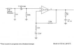
Well, I made some progress!
Okay,
I used NFB of
220k, 4.7k and 22uf (didn't swap out the caps yet).
Input of
skipped the pot for now, left the 1m resistor (shunt) that comes with the K50-LM1875, 3.3uf, 100k input load.
Folks with a preamp might enjoy trying that. I sure did. Its gorgeous.
For the project, its not enough gain. Darn!
I had used National's spreadsheet set on LM1876 to try to match up. Well, that thing is pretty far off.
So, I raise the gain by changing 220k (above) to 270k, and got that certain stinky coloration for when there's too much voltage in the NFB.
For this problem, Andrew told me to get lower (and a lot of other things I have yet to comprehend).
So, I did
NFB
120k, 2.2k, 22uf
Still a gain boost, but not quite so much.
The coloration is gone! Thanks Andrew!!!
We now have a fairly matching 100k layout, with the exception, the error in the spreadsheet making the NFB go to 120k, instead of 100k, for expected results.
There's probably enough gain now that the input circuit will work as pictured (protect the amp). I just don't know yet. I need to go to the store for parts.
This (NFB resistors) was a serious power boost without creating more coloration than there's tolerance for in the LM1875.
As in the first layout the presentation is center stage, like a Thompson or Tripath.
Its about time.
Oddly enough, the power boost mod has the terrifying command of bass and dynamics like a Tripath pushed beyond maximum theoretical voltage.
Never thought an LM could do that!!
A difference from that result, is that LM1875's slight brashness is right into the middle band, cancelling the potential coloration from the power boost. . . so the previously absent warm "phrat" sound has arrived. The high treble remains intact, but is now in proportion--still with "air to spare." Most amazing.
Voltage tested is 29+29 DC (a 36v center tap), and she's seriously pulling down the transformer during dynamics. It probably means that I've just found the actual limit during a 4 ohm load.
Next, I'll need some help to improve the efficiency.
Its still open and vulnerable (to possible inefficiency that could limit useful power via clipping), so the input circuit and the two caps I'm working with, need some discovery.
Specifically, there's way too much bass down at the very lowest parts of the audio band for a little amplifier to be doing. I'll need to cut into that slightly to get some more headroom and SPL.
Here's what it looks like right now.
Attachments
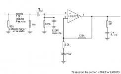
With 100K input Z you can get away with 0.47uF input cap , - 3db at 3.4 Hz .
3.3uF seems to be over kill ! I doubt you would hear any difference in the low end. Chances are that the 0.47uF might sound better , maybe !
3.3uF seems to be over kill ! I doubt you would hear any difference in the low end. Chances are that the 0.47uF might sound better , maybe !
Ashok does a better job of listening.ashok said:With 100K input Z you can get away with 0.47uF input cap , - 3db at 3.4 Hz .
3.3uF seems to be over kill ! I doubt you would hear any difference in the low end. Chances are that the 0.47uF might sound better , maybe !
The two input filters set the bandwidth of the amplifier.
The input cap should be reduced from 3u3F to <=0u33uF to better match the RC of the NFB.
I wonder if replacing the 47uF with the smaller/better 22uF is what got rid of the colouration, rather than changing the resistor values.
The RF filter is still missing.
Can I post schematic from a magazine?
EPE April 07
Student's amp
14hZ to 100kHz, <0.04% total harmonic dist. 105bd signal to noise 20W RMS
If it will help they sell PCBs at GBP6 for amp and PSU, I will gladly attach ordering URL. to balance out their rights
EPE April 07
Student's amp
14hZ to 100kHz, <0.04% total harmonic dist. 105bd signal to noise 20W RMS
If it will help they sell PCBs at GBP6 for amp and PSU, I will gladly attach ordering URL. to balance out their rights
Nordic said:Can I post schematic from a magazine?
EPE April 07
Student's amp
14hZ to 100kHz, <0.04% total harmonic dist. 105bd signal to noise 20W RMS
If it will help they sell PCBs at GBP6 for amp and PSU, I will gladly attach ordering URL. to balance out their rights
Thank you!!
We'd have to ask a moderator to be sure.
But, you can post an advertisement for a LM1875 module or kit--that's right on topic, because its a resource.
And then, we can discuss the resource. 😉
I also have my own version of the circuit, done in eagle.. so it would circumvent the copyright related to duplicating their artwork...
AndrewT said:Ashok does a better job of listening.
The two input filters set the bandwidth of the amplifier.
The input cap should be reduced from 3u3F to <=0u33uF to better match the RC of the NFB.
I wonder if replacing the 47uF with the smaller/better 22uF is what got rid of the colouration, rather than changing the resistor values.
The RF filter is still missing.
This is the LM1875 k50 kit that I'm working on. The NFB capacitor was not changed from 22uf during the testing. It was the resistor values. What a great clue!! Thanks!
Results of the testing (chart above) have increased the headroom and dynamics up to good hi-fi. 😉 I was a little bit tired last night. That's where I went to bed and let Enya play all night long. Egads at the dynamics! There was some sort of fake thunderstorm that went X-Max and frightened me in the night. lol!!
Today, I will add 100k load in front of the input to represent a 100k pot that's wide open. That's how I'll start today.
And, hey!! Thanks for the next clue! I'll test 4.7uf and 10uf values in the NFB, just to see what happens. I want the restriction inside the audio band--just barely.
On the input filter. I hear ya! But, last night, I heard the amp start to need it. Possibly 0.22uf polyester 250v InterCap for input filter?
The soldering irons are hot. See ya later! 😉
With/without the input load (that represents a potentiometer)--regardless of that. . .
4.7uf in the NFB returned the "always in front" typical gainclone kit sound, with precision, no colorations, no headroom increase. . . no transparency, and no point. Oops. Well, there's a useful paramater of what doesn't work.
Will test 10uf there next--no expected headroom increase; however, a return of transparency and lack of coloration would be a nice combo.
If that doesn't work, I'll return 22uf.
Either case, I'll report back.
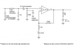
Working baseline!!!
Transparency is apparently maximal with the 22uf that comes with the K50 kit.
10uf "moved" the coloration upwards in frequency, but didn't remove it.
Therefore, NFB (gain loop structure) is:
120k
2.2k
22uf (already included with K50 kit)
Can you guys check my figures? Thanks!!
Zobel effect observed--frequencies above those indicated by the software/spreadsheet are boosted.
22uf directs this right at the very lowest notes of the audio band.
47uf goes into theta wave territory (wasteful and colorized).
10uf gets the upper midband as a shout.
4.7uf does the treble--not quite high enough to be useful.
So,
22uf was best.
Whoops!
The soldering irons were still on. . . and so was my imagination. 😉
Can you check this chart instead?
The power has finally arrived, and the coloration took a hike (gone). But, is it really supposed to be doing 78 watts?
Howabout 0.068uf mylar input filter cap instead of the 0.22uf polyester? Is that closer to specs than shown?
Thanks again!
Attachments
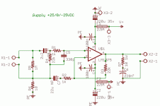

Nordic--yeah! Let's see it. 😉
Hey Nordic man! Go for it. Its nice to see different designs for comparison.
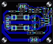
And, here's what I'm jamming out to tonight. 😉
Thanks to Andrew and many others who helped me!
I'm very, very happy.
Big dynamics, much power, and finally hifi with sheer force! 😉
This puts my two tripaths, two tube amps, three transistor amps, one thompson amp, a class-D project, and most certainly LM3886's--to shame. Here she is:
Nordic said:I also have my own version of the circuit, done in eagle.. so it would circumvent the copyright related to duplicating their artwork...
Hey Nordic man! Go for it. Its nice to see different designs for comparison.
And, here's what I'm jamming out to tonight. 😉
Thanks to Andrew and many others who helped me!
I'm very, very happy.
Big dynamics, much power, and finally hifi with sheer force! 😉
This puts my two tripaths, two tube amps, three transistor amps, one thompson amp, a class-D project, and most certainly LM3886's--to shame. Here she is:
Attachments
Nordic said:schematic attached
Wow! Can you make 2x for parallel amps on 28+28vdc?
- Home
- Amplifiers
- Chip Amps
- Thoughts On LM1875 Gainclones