...........................................................................................
WOW, I'm zapped . Suddenly I seem to find it really hard to comprehend what's being written.
Are my gray cells failing me ?
WOW, I'm zapped . Suddenly I seem to find it really hard to comprehend what's being written.
Are my gray cells failing me ?
No, its not you. I had a difficulty in expressing that I needed more gain in order to avoid clipping.
which is opposite to:- I used more gain to promote clipping.danielwritesbac said:I needed more gain in order to avoid clipping.
I think you may find that circuit a pleasant surprise.. not only does it block, too low frequencies (resembles DC)... it blocks HF noise on the input, it blocks DC and provides a path to ground for the DC on the input, which is lower resistance than trying to go through the amp...
Gain should never try to force the amp to full voltage rails, (not even for dynamic peaks - well... maybe in a nice softclipping tube amp)
Gain should never try to force the amp to full voltage rails, (not even for dynamic peaks - well... maybe in a nice softclipping tube amp)
Wow. I'm a little embarrassed that I didn't notice that the GAIN was set to 53.3(!), during my earlier comments.
Daniel, do you have any test equipment, such as an oscilloscope? Distortion analyzer? It might be helpful for you to download, and burn a CD with, some audio test signals. Or you could use your computer's sound card, maybe for both the test signal generation AND the oscilloscope and distortion analyzer. There are free downloads to make your soundcard do both, although they are relatively crippled by the low bandwidth of the soundcard. But, even with just a voltmeter, you could measure the RMS amplitude of a lower-frequency sine-wave test signal, at both your input (source output) and your output.
Someone correct me if I'm wrong, but, it seems like, with your relatively-high gain of 53.3, and 29-volt rails, an input amplitude of only 0.106 volts zero-to-peak or so (only about 0.075 volts RMS) would give you an output amplitude of almost 5.7 v pk (4 v RMS), which would be dissipating about 32 Watts into an 8-Ohm load, and would then have 1% distortion. (See the graph of "Power Output vs Supply Voltage", on page 3 of the LM1875 datasheet. See, also, the graph entitled "THD vs Power Output", just above that.)
So, probably, with any input amplitude larger than 0.106 volts 0-peak or so, even though the output technically might have some headroom to go higher than 5.7 volts peak, for a short time, the result would be distortion (of the peaks, at least) that's significantly higher than 1% THD (which is already too high). It might be somewhat difficult to discern, with a music source. But a relatively-pure sine source might make it clearer, so to speak.
Then maybe you could try adjusting both the gain and the input amplitude, so that the output peak level always stayed the same, to see if you can hear any difference between different gain levels. (i.e. I think you would want to adjust both, to keep the output amplitude the same, to give a "level playing field" for evaluating the differences between gain levels, if that is what you are after.)
Nordic said:I think you may find that circuit a pleasant surprise.. not only does it block, too low frequencies (resembles DC)... it blocks HF noise on the input, it blocks DC and provides a path to ground for the DC on the input, which is lower resistance than trying to go through the amp...
Gain should never try to force the amp to full voltage rails, (not even for dynamic peaks - well... maybe in a nice softclipping tube amp)
Quite good! I would like to try it as the drive for a FET or Hypex.
gootee said:Wow. I'm a little embarrassed that I didn't notice that the GAIN was set to 53.3(!), during my earlier comments.
. . . Or you could use your computer's sound card, maybe for both the test signal generation AND the oscilloscope and distortion analyzer. There are free downloads to make your soundcard do both. . .
Someone correct me if I'm wrong, but, it seems like, with your relatively-high gain of 53.3, and 29-volt rails, an input amplitude of only 0.106 volts zero-to-peak or so (only about 0.075 volts RMS) would give you an output amplitude of almost 5.7 v pk (4 v RMS), which would be dissipating about 32 Watts into an 8-Ohm load, and would then have 1% distortion. . .
Thank you!
Yes, that's right. Power versus fidelity limit on the LM1875 chip gain seems to be 47.5 (gain).
However, (and in my opinion) the actual consequences of too high gain on LM1875, as in past 50, sounds like LM3886 at normal gain.
In contrast, LM1875 gives me the choice. What a relief!
See the clue I left "depends on desired output" straight on the middle of my LM1875 charts. I did mean "desired." 😉
I'd surely like to know of these free downloads for soundcard. Do you think that 23hz to 23k at digital 96k speed is enough resolution?
Hey guys, howabout this? Full range drivers test.
Test groups and full-ranger's today. . .
Several different designs tried.
What do you guys think of this?
P.S. I just got back home, plugged it in and played Enya for the cats. They went feet-up sound asleep in record time. 😉
Test groups and full-ranger's today. . .
Several different designs tried.
What do you guys think of this?
P.S. I just got back home, plugged it in and played Enya for the cats. They went feet-up sound asleep in record time. 😉
Attachments
I am puzzled. I don't know why anyone would want to use a carbon composition resistor in an audio signal chain. Metal film resistors are far superior, in every way I can think of. If the carbon composition resistor "sounds better", maybe that's because it is helping to mask the sound of some other problem.
<flame-suit on>
🙂
<flame-suit on>
🙂
Oh, I think you're right.
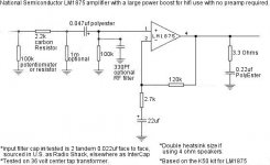
However, Rb (input in-series) is often helpful as carbon because its a further isolation from circuits of the source. That depends on the source, but it is measurable. That's why the 2.2k specifies carbon and the others don't mention material.
For the empirics, carbon provides a "laid back" presentation. That can be important to amplifiers that have trouble with a realistic presentation of depth, and fix them. Look who needs a flame suit now. 😉
Hi Daniel,
what does "2 tandem face to face" mean?
A parallel pair of 22//22nF=44nF.
A series pair of 22+22nF=11nF.
what does "2 tandem face to face" mean?
A parallel pair of 22//22nF=44nF.
A series pair of 22+22nF=11nF.
AndrewT said:Hi Daniel,
what does "2 tandem face to face" mean?
A parallel pair of 22//22nF=44nF.
A series pair of 22+22nF=11nF.
Parallel. I'll fix the language.
Hey, are you giving this one a listen? I really like it.
EDIT: I think its a pair of polyEster, "face to face" meaning that the labels touch (one is reverse polarity), that is the more level response in conditions that involve sources with strong DC output. But, really, I just did that because it sounds pretty. 😉
danielwritesbac said:
Parallel. I'll fix the language.
Hey, are you giving this one a listen? I really like it.
EDIT: I think its a pair of polyEster, "face to face" meaning that the labels touch (one is reverse polarity), that is the more level response in conditions that involve sources with strong DC output. But, really, I just did that because it sounds pretty. 😉
Sorry if it seems like I'm "turning negative", here, Daniel. And I'm sure that you have more-interesting things to think about than this. But those polyester capacitors should not have ANY "polarity", in any measurable or audible sense that I'm aware of. It's even quite possible that the labeling is printed on either side, randomly.
But, I usually try to be open-minded. If you give us their make and model, maybe we can check the manufacturer's website, or research similar types of caps, and see if there might be any asymmetry in their construction, that might account for some noticeable or measurable "polarity" effect.
for DC block on the input?danielwritesbac said:I'd like to try BlackGate. .... do you think that 0.1uf would be okay?
You already have the formula tying cap and resistors values to the F-3db rolloff.
I think you might get a bigger improvement by deleting the electrolytic in the NFB DC blocker and try selecting a decent film cap value that still allows your chosen but restricted bandwith to pass.
gootee said:. . . But those polyester capacitors should not have ANY "polarity", in any measurable or audible sense that I'm aware of.. . .
Should not? I agree! 😉 Its annoying and variable as to which film cap will demonstrate a different response to an AC signal depending on polarity. In using a pair from the same production run, face to face (label to label), it "should" zero the variance.
Its my "make it easier" approach to the bypass cap practice, working fairly reliably when you need a small value like 0.047uf. This also seems to work with some, but not all, mylar caps.
Edit: The make is listed on the design chart, very widespread retail availability in the U.S., so they're quite accessable. The 0.022uf even come in packages of twos. They're small, they're green, they're decent, and they're nearby. 😉
Edit2: The larger, green, 0.22uf version plus a wirewound pot can make for an interesting output zobel. I use the pot (as a variable resistor) to figure out what resistance value is nicest as far as audiable effect--and then substitute a resistor of that value.
There's also a very large blue 1uf film cap that works quite nicely for input caps on Tripaths, although its unhelpful to conquer the midrange on gainclones.
Andrew, WOW!
Perhaps I misinterpreted? This was quite the amazing audio experience. Yes, I'm enjoying the new speaker drivers very much. And, its no longer a secret what the "X" marks are for on the tops of caps. Simultaneously exploding caps and exploding loudspeakers. . . is sufficiently loud.
AndrewT said:for DC block on the input?
You already have the formula tying cap and resistors values to the F-3db rolloff.
I think you might get a bigger improvement by deleting the electrolytic in the NFB DC blocker and try selecting a decent film cap value that still allows your chosen but restricted bandwith to pass.
Perhaps I misinterpreted? This was quite the amazing audio experience. Yes, I'm enjoying the new speaker drivers very much. And, its no longer a secret what the "X" marks are for on the tops of caps. Simultaneously exploding caps and exploding loudspeakers. . . is sufficiently loud.
This led to a nice development.
It seems that the NFB cap (22uf usually), can have a wider effect on sound than any other part.
I had great luck by putting a high-end cap in this location.
However, economy electrolytic caps (and some film too) seem to come in two "sounds" much midrange or much bass.
Of these, the "much bass" varient (already onboard K50) benefits with an inexpensive bypass cap (parallel) of about 0.01uf or smaller (polypro, polyester, or exotics)--can be almost like a high-end cap's big warm presentation with much detail (not honking) in the upper treble. 😉
The bypass cap practice backfires badly if its tried with a "main" cap that is the "much midrange" variety because you get the goshorn sound; however, if this is noticed, its good information as to the part to remove/change/upgrade.
Say, Andrew, thanks for this additional avenue of discovery.
I must say that the LM chips are surprisingly sensitive to the nature of their capacitors. Layouts like 220k NFB can decrease this sensitivity a bit for those not wanting as much capacitor shopping adventure.
I wonder if the LM chips are also more revealing on the source materials than the tripath or thompson chips (which aren't as sensitive to cap sounds)? Perhaps I haven't found out yet.
This was the last of the clues needed in order to proceed with the surround sound project and match up the characters of several different amplifiers.
Thanks again!
Daniel,
Have you not experimented with different sizes, types, and positions of bypass caps, for the LM1875's power pins? Or did I miss that part of the thread?
Besides the more-obvious possible frequency-response effects, I have read that the LM chipamps might be quite sensitive to inductance, there, which would vary with cap type, size, lead-spacing, and, lead or trace length and bulk.
You might also want to try using RC snubbers, in an attempt to "cancel" any inductance from what leads to the power pins. The famous CarlosFM swore by them.
gootee said:Daniel,
Have you not experimented with different sizes, types, and positions of bypass caps, for the LM1875's power pins? Or did I miss that part of the thread?
Besides the more-obvious possible frequency-response effects, I have read that the LM chipamps might be quite sensitive to inductance, there, which would vary with cap type, size, lead-spacing, and, lead or trace length and bulk.
You might also want to try using RC snubbers, in an attempt to "cancel" any inductance from what leads to the power pins. The famous CarlosFM swore by them.
I have the chipamp.com power supply with his name on it. Its nice but doesn't help the forwards midrange of the LM chips. I also have the two matching burglar alarms that come with it. Shame on me for being so gullible.
However, the LM1875 is somewhat better. What really did make a difference was to use an outdated Panasonic "epoxy bottom" audiophile cap at Ci for LM1875. This actually put forth some high fidelity. What a nice surprise!
Since there are no more of them, there's no more LM chips for me unless a substitute cap or other workaround can be found.
Thanks for all your help, but I am at an impasse with the LM chip amplifiers.
- Home
- Amplifiers
- Chip Amps
- Thoughts On LM1875 Gainclones