Another reason for the difference in transient bite could be due to the change in LF response. Without the input cap the input signal LF goes down to dc. With the cap included the LF starts to roll off and also causes a 'time' shift ( phase shift ) . So with cap the LF drops slightly causing the signal to sound brighter ? ..............or would it be HF distortion artefacts generated when transients pass through the cap ?
ashok said:Another reason for the difference in transient bite could be due to the change in LF response. Without the input cap the input signal LF goes down to dc. With the cap included the LF starts to roll off and also causes a 'time' shift ( phase shift ) . So with cap the LF drops slightly causing the signal to sound brighter ? ..............or would it be HF distortion artefacts generated when transients pass through the cap ?
At position "C"
Well, you'd have to severely cut into the LF before you get a brighter sound. If using a polypro cap, instead try a 100v, 4.7uF ecap with a 0.01uF polyester cap (or with a 0.0068uF polypro).
If that doesn't do it, try a 250v rated cap.
That ecap/polyester combo isn't a perfect value for input filter cap, but it couldn't remove bass notes. In some cases, it could make a very slight loudness contour effect.
Can you describe the empiric effects of "transient bite"? At what frequency is it (an unwanted boost?) most noticable?
I'm guessing that "transient bite" isn't occuring at 35hz. 😉
P.S. Hey, I sent you an email.
Daniel,
Could you explain what the voltage rating of a cap has to do with sonics? Also, what’s the formula you used to come up with the values of the different capacitors you used.
/Hugo
Could you explain what the voltage rating of a cap has to do with sonics? Also, what’s the formula you used to come up with the values of the different capacitors you used.
/Hugo
Hi,
removing the input DC blocking cap changes an AC coupled amplifier to a mixed AC& DC coupled amplifier.
Worse, the input high pass filter defined the low frequency bandwidth.
Removal of this passive bandwidth limiting, moves the high pass duty to the NFB cap that blocks DC inside the amp.
I would expect the sound to be different.
I would further expect to be able to measure significant AC voltage across the remaining DC blocking cap in the NFB loop.
I suspect the increase in distortion that this causes may be audible and could explain the difference in sound noted.
I do wonder how many times in the last year or so I recommend AC coupling and next best is DC coupling with detection and shut down if the DC passed to the output becomes excessive. Mixed AC & DC coupling can never be recommended. Although Carlos does promote it conditional on following all his build advice.
Netlist said:Daniel,
Could you explain what the voltage rating of a cap has to do with sonics? Also, what’s the formula you used to come up with the values of the different capacitors you used.
/Hugo
Hi Hugo! I'll do my best to explain it.
Size of cap:
With Xicon as an example of a recent trend, 25v or less ecaps are being sold with 50v labels. This overstressed cap can affect sound. Here, popular vendors like Radio Shack and Parts Express carry Xicon. Even the most reliable vendors like Allied Electric do have some examples of oversold caps, like Illinois Capacitor Co.'s new "convenient smaller size" caps. Fortunately, they also offer "full size" caps.
Voltage rating relates to size of cap:
It is most likely that a higher voltage rating may get you the cap that you actually intended to purchase, and that could get you closer to expected behavior from the amplifier.
General input filter cap:
The formula used to come up with the input filter cap suggestion is simply a survey (average approximates) of what's most likely to work when all of the other variables are either unknown or not working as expected. And, I mentioned that it wasn't a perfect value for input filter cap.
Also, its probable that the practice of "too large" 4.7uF input filter caps on diyaudio.com relates to general artifacts in ecaps. Ecaps will usually boost their upper response greater than their lower, so a potential solution is to aim lower on purpose. That will fail to work correctly about 1/3rd of the time (generally), because it will cut off some treble if the cap in use isn't made for audio signal.
This is why I also mentioned using a small bypass cap.
I suggested polyester for the small bypass cap because of its high ESR. That way, if the ecap is more efficient, then the polyester bypass cap will not pass signal; however, if the ecap is less efficient, then the polyester cap will be more active. This scenerio is different with polypro (usually more efficient than an ecap), so I suggested a smaller (less effective) value if polypro is used for a bypass cap.
I'm dizzy now. 😉
Daniel,
Thank you for trying but:
To me, an amplifier should reproduce the audio band as faithful and linear as possible.
Trust me that the voltage rating of a cap has nothing to do with the sonic signature of an amplifier.
I strongly suggest you do some basic reading on electronics. I regularly refer to Perry Babin’s site http://www.bcae1.com/
I’m dizzy now, too. 🙂
/Hugo
What's transient bite?
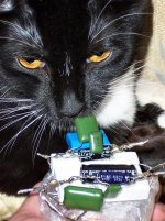
Edit: See fun pic of new speaker crossover using "bypass cap" to an extreme. Of these, the blue 1uF on tweeter, and black 10uF on woofer can't get bucked. This is for a laid back sound, with wide disperson, long throw and transparency. A side effect is that its a "live" crossover, shifting audio signals between woofer and tweeter, so it doesn't work well at close range. However, transparency is good at longer range (distance from speaker) than usual. Its an extreme application of bypass caps for larger-size rooms or PA. 😉
Edit: See fun pic of new speaker crossover using "bypass cap" to an extreme. Of these, the blue 1uF on tweeter, and black 10uF on woofer can't get bucked. This is for a laid back sound, with wide disperson, long throw and transparency. A side effect is that its a "live" crossover, shifting audio signals between woofer and tweeter, so it doesn't work well at close range. However, transparency is good at longer range (distance from speaker) than usual. Its an extreme application of bypass caps for larger-size rooms or PA. 😉
Attachments
Daniel ,you sure explain things in a very unusual way. I find I need to use unexplored parts of my brain to unravel what you mean. Great mental exercise !
Looks like it drives some people nuts 😀 .
However you really are having fun and we'd like to continue participating and share the fun!
I replied to your PM just now.
Cheers.
Looks like it drives some people nuts 😀 .
However you really are having fun and we'd like to continue participating and share the fun!
I replied to your PM just now.
Cheers.
The main point
Simply put, for caps at C and Ci, if you use a cap that omits the bass, a much smaller bypass cap won't help it. If the capacitance value is correct, then this cap is inefficient at passing bass (higher ESR at bass).
However, if you have a cap at C and/or Ci that omits some treble, then a small bypass cap will fix that (higher esr at treble + addition of more efficient treble = mostly flat frequency response)
On the ESR charts, ecaps with higher voltage ratings pass larger bandwidths, and are less likely to remove either bass or treble. They also have lower average ESR (overall higher efficiency = less possible variance in frequency response) in direct proportion to increased physical size (generally). Thus 100v caps at Ci.
Check out the charts.

ashok said:Daniel ,you sure explain things in a very unusual way. I find I need to use unexplored parts of my brain to unravel what you mean. Great mental exercise !
Looks like it drives some people nuts 😀 .
However you really are having fun and we'd like to continue participating and share the fun!
I replied to your PM just now.
Cheers.
Thanks for the compliments. I do have the darnest time explaining what I mean. 😉 But, still, exploring amplifiers is greatly interesting fun.
Nordic said:guess I'd better go rip out my 600V Ampohm caps then........
Wow. I didn't say anything about big caps. I don't know what happens if you put a huge cap at C or Ci. But, I'd really like it if you'd describe the benefit/effects. 😉
Originally posted by Netlist
Trust me that the voltage rating of a cap has nothing to do with the sonic signature of an amplifier.
I'm not going to say that changing the voltage rating of an input capacitor will make an impressive difference in the sound, but i've heard some chinese-made underrated ones to perform very badly. This will probably be due to the poor ability the cap has to withstand reverse bias.
I have also posted a reply to danielwritesback somewhere around with a link to a web page that compares the linearity of some caps and it has some scope-pictures of a ceramic HV-rated and a LV one and the difference is clear there. Fortunately electrolytics behave better than X5R/X7R ceramics but this does not mean that there aren't any differences with voltage rating.
I must say i'm completely against the "cult to the cap" that plagues many audiophiles.
ionomolo said:I must say i'm completely against the "cult to the cap" that plagues many audiophiles.
I don't like it either, although it can be useful.
I have been unlucky at getting the point across that there's no use in purchasing a selection of deluxe input filter caps if you happen to have modernized undersized junk at Ci.
For a replacement at Ci, I'd like to use an application specific part with the opposite sonic signature of the amplifier, a high performance that is documented, and a low price (less than $1).
Why is it that we don't agree on that?
Edit: Thanks sincerely, for explaining the reason for the size/voltage observed benefits of larger size caps as a difference in withstanding reverse bias.
G'day to all
Just on the input cap thing I have tried a few and really found very little if any difference, however I do feel that a decent mylar type cap seems to work quite well. I have also used banks of smaller mylar value caps in parallel and found that when I removed the caps from the circuit altogether I could hear no change. Which I guess means they were doing a good job as after all the cap should not be adding to or degrading the sound.
Using cheap electros did cause a degradation when compared to no cap at all so not the ideal solution.
The caps do however make a big difference in the power supply/bypass end of things so bigger voltage ratings are probably well worthwhile, I must add however that overly large value caps definitely kill some midrange magic. The size of the caps you can get away with in my experience is very dependent on the type of power supply your using.
In my mind and experience the real gains in performance are made via better power supplies and detail to the smaller aspects of layout, shielding etc, fortunately none of this makes the amp expensive.
As an aside one little amp idea I am currently looking at is a bridged version of the LM1876 chip, this for those who may not have come across it is basically a pair of 1875s in one package with some better(?) protection circuitry and muting built in.
Here's the neat bit, my experiments have shown me that the LM1875 is really sweet and tube like on 12 to 16 v battery power (if built appropriately) but of course this limits power to around 6 watts........but bridge the chips of the LM1876 and you get around 24 watts on the same voltage, providing of course you have enough current. I suspect such an arrangement combined with a pre amp with a highish output and some efficient full range drivers would have some real sweet dynamics and impact.
Overall I must add that I look at my amps as part of the complete system so basically I am looking for a synergistic coupling that takes into account the source, pre amp, power amp and speakers, the great thing is that it is pretty easy to cook up an amp the fits the need specifically using these chips.
Zero One:
Just out of curiosity , what input impedance does your Lm1875 amp have.
What value / brand caps do you use for the input and dc block at the NFB .
The power supply capacitors will affect the charging spikes from the transformer/rectifier diodes. A larger capacitor will have shorter duration spikes ( for a particular load ). So the HF trash on the supply will vary with capacitor size.
So circuits with very high PSRR might not loose out in signal quality with larger value supply caps (?).
Cheers.
And, what do you generally favor for NFB values?
Generally, I find that 100k (with 2.2k) on the input, and then 120k (with either 2.7k or 3.3k) in the NFB is a pleasant combo.
That same input, and then a NFB of 220k (with 4.7k) has a distinctly Fletcher-Munson effect. However, values in-between 220k and 100k can be quite bright--not the wrong sort of bright, but just an excess. For instance K50 ships with 180k at NFB, and that's analytical, almost the point of raspy.
I'd love to know the reasons why, and/or what others are using for these fine tuning options.
Thanks!
These values are by far too high and will introduce a lot of offset and noise. Choosing too low values means that the cap may pass a lot of current and distort more, but choosing huge ones isn't a good solution for sure. Look at the new driver datasheet:
http://cxem.net/doc/amp/LME49810.pdf
To see which values are suggested by national for the feedback resistors.
National has moved to lower values in theyr high-end designs because higher ones are noisy. There are great articles about thermal noise in resistors, give them a look.
http://cxem.net/doc/amp/LME49810.pdf
To see which values are suggested by national for the feedback resistors.
National has moved to lower values in theyr high-end designs because higher ones are noisy. There are great articles about thermal noise in resistors, give them a look.
ionomolo said:These values are by far too high and will introduce a lot of offset and noise. Choosing too low values means that the cap may pass a lot of current and distort more, but choosing huge ones isn't a good solution for sure. Look at the new driver datasheet:
http://cxem.net/doc/amp/LME49810.pdf
To see which values are suggested by national for the feedback resistors.
National has moved to lower values in theyr high-end designs because higher ones are noisy. There are great articles about thermal noise in resistors, give them a look.
Thank you so much! That's absolutely fascinating and I will try it on my next LM chip study.
On first glance, it seems that NatSemi has created one heck of a noise at Ci, but also "pushed" it below the audio band, while also using a cap large enough to handle the problem--that is potentially more significant than the resistors. But, lets try it!! 😉
Have you tried this layout on LM1875?
EDIT: And, what is the effect on dynamics?
Originally posted by danielwritesback
On first glance, it seems that NatSemi has created one heck of a noise at Ci, but also "pushed" it below the audio band, while also using a cap large enough to handle the problem--that is potentially more significant than the resistors. But, lets try it!!
Electrolytic caps should be more or less 5x its theoretical value to avoid capacitor distortion. This has been posted arround at least ten times.
- Home
- Amplifiers
- Chip Amps
- Thoughts On LM1875 Gainclones