dear SIR
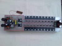
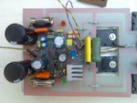
greetings i want to tell you dhr turbo was tested no oscillations very detailed
sound bass and highs very detailed 10 output pairs
1 transformer used 400 va 50 0 50 ac
2 speaker impedance 4 ohms
today i will be winding my torrodial transformer 1200 va tappings 50 0 50 60 0 60 70 0 70
condensers 50000 each on each rail
for heat compensation instead of 4 diodes in series can i use high speed diodes BYW 80
easier to mount or transistor 2sd381 or transistor 2n5294
CAN the supply voltage be pushed further say 60 0 60 ac with some modificatons
THANK YOU for providing diyers such a GOOD SCHEMATIC
thanking you
andrew lebon
pictures will be posted today
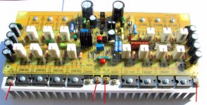
dhr turbo 10 pairs in output
pics of turbo
pics of turbo
Attachments
Last edited:
Yessssss...you can push it over the limits of voltage!
Have to check all transistors if they can work under your new voltage..also if they can dissipate the power (current multiplied by the voltage you have measuring colector to emitter... current is the one crosses colector to emitter)
Have to replace all electrolitic condensers by higher voltage ratio.
Have to include heatsinks into drivers, Vas and reinforce your output heatsink size and your transistor pairs may need (maybe) some more pairs... depending the speaker impedance and depending the supply power capacity.
A huge KILOWATT channel!
Have to increase the resistance that feeds the zener...install 5K6 or 6K8 in the place your schematic suggested value..... or increase your zener wattage capacity, install 5 watts zener and nothing to worry about...solder the one distant from the board...doing this you will not need to increase your zener series resistance (the one limits the current).
Prepare yourself to 1100 watts rms over 2 ohms loads..but you gonna need a 2 Kilowatt transformer to do that!....also you gonna need some pairs more to be safe... 10 pairs may hold the job..but i am not sure, as i have not tested such level of power here..i have not transformer able to provide me all that current......of course this depends the 84 volts simetrical stable (no drop)...and this never happens in real life....well...prepare yourself to a very huge power..able to melt speakers.
Thank you very much, the review and also the pictures..i am happy and dancing knowing you have aproved the amplifier and that you are feeling good.
regards,
Carlos
Attachments

Thank you by the lovely pictures.
Remember ... the output power depends on the supply power...if your supply is no good, them the power will be small..install several transformers... use separated rectifiers and join the rectifier output (dc) into the filter bank of capacitors to obtain the power you want.
There's no big magic possible... into AB amplifier the power will be 55 to 65 percent power your transformer can supply.
regards,
Carlos
Attachments

Last edited:
if results are coming out so good from a schema like that from uncle charly may be a join effort of uncle charly and other forum memebers to equip the DHR Turbo with some aditional protection methods like VI limiters or so in order to create a semi professional version of the DHR...
what do you think ???
what do you think ???
I can make that VI limiter...i do not like them...but i can do it to the ones
interested...i think they compress...i really dislike the sonic result... results that you increase your volume and the treble go increasing while the bass remain in the same level...bass is the biggest (amplitude, size, voltage) signal present into music...so, bass is the signal that goes triggering the hell circuit that goes controling....then you increase volume, only the treble is increased... as bass is triggering and circuit is behaving alike an automatic gain control....terrible!... personally, if i can say dear Sakis, i feel these things disgusting.
Each power will need a special adjustment to the VI limiter...so, if the amplifier will operate with 60 volts you have an adjustment, another amplifier operating 84 volts will ask another adjustment.....well.... a single trimpot to each channel.
Yeah!..i can do it if someone is interested.
I never did because i am not interested...but of course, if a Dx friend, the ones are building Dx amplifier or will really construct...for those ones i can produce, gladly, the circuit...it is simple, traditional and i can even copy from others and adjust.....the adjustment, to each amplifier, is the most important thing...not to be triggering soon and limiting the power amplifier dinamics..power may go to 1 percent distortion before the circuit go triggering.
VI limiters are often used to protect output transistor..because factories use only one pair, or not enougth pairs...this is not our case..... for them, the VI limiter are precious not to burn the factory image having amplifiers burning in series.
I think, to our amplifiers, the forum units, all them very well made related the power reserve into the output transistors, ... well...our does not need to protect the output....a good idea is to control de peaks not to enter higher levels of distortion than 0.2%... or 0.3%.... or 0.5%.... well...the customer says what they want and we inform the resistance values.
I do not remember Sakis, but maybe Quasi amplifiers have the VI limiter...also Rodd Elliot units.... we need just to copy and adjust the resistances the way we want..the main one to adjust is the series one that goes to the VI limiters transistor base, or the voltage divider that drives these bases.
regards,
Carlos
Last edited:
a design like that might be a very interesting idea ...
as it is very well known all protection methods will remove some ammount of quality from any amplifier .From various protection methods there is going to be various drawbacks for a number of reasons
also let us not forget that a professional amplifier has to be designed to work 100% or more power almost at all times which also brings in mind that none of the amps presented in the forum will ever manage a thing like that I presume that most of forum amplifiers are designed for a more audiophile approach
so here come the designers skills to produce protection methods that are quick and effective while destroy as less is possible from your amplifiers quality and sonics
yet gain i will place my statement regarding the design of professional amplifiers where id like to say that schematic of an amplifier is only 30 % of the deal ....how to protect a ...poor design is the rest 70% Most comercial cheap professional amlifiers work like that ...
Quasi amplifiers uncle Charly do not feature a VI limmiter or similar protection ....still id like to say that 4 pcs built so far runing almost a year now for small PA applications that we take as a fact that are getting abused ....never failed i dont know if this is a benefit of a Quasi design but playing arround with 300 or more watts is not an easy task to do without limmiters still no problem yet
( it is also inetersting to say that the one of the quasi i built is very poor designed since the psu is too small to operate the amp at full load ....of course pushing the amp to the limmits will result that poor psu will not provide enough power to create damage and act as a limmiter while distortion figures rise to the moon ..... the rest three though are created with very good material big trafos 1500 w and huge caps 75.000 +75.000 way too big for a comercial amp and still absolutelly no problems with them ....the task is Pa monitors in small stages , party, vocals , weedings and so on )
regards sakis
Last edited:
All Dx amplifiers are already made designs, we are not into the design stages
anymore... so, the amplifiers will not receive modifications into the schematic.
If someone wants that protection, i will make this customized to the one wants, if i perceive serious intentions the one will build not to waste time providing customized designs that will never be assembled.
Dx amplifier is not a professional unit, it is a DIY unit, made for fun and to the enjoyment of our forum friends into the audiophile and diyers communitty.
I will not kill Dx unit sonics, including that hell thing into the regular,standard schematic, it is reliable and safe the way it is to non professional use or abuse, and people is buiding because it is a "non mutant circuit"..since was published it was keept the way it is, nothing changed.
When you go changing schematics nobody assemble Sakis, watch what happened with several designs we have into the forum, nice ideas posted, good amplifiers, but with several versions, almost no one have assembled....Dx amplifier have already more than 150 units built.... and one of the main reasons...non mutant schematic..very frustrating when you assemble something and the next day it is obsolete.
If you're needing something alike, dear Sakis, let me know, tell me your transformer power and voltage (tested under load) and i will make it to you...but you assemble and please, do not say people that inside the case is a Dx amplifier playing.... and i will be very clear...will do that for you because a good friend..but not happy with such kind of story.
Go direct to my email adress, to avoid people to copy the hell thing, that will result counter productive related the sonic sweetness that are traditional to the Dx amplifiers...and one of the reasons of this nice sonics is that i always have avoided any kind of limiters.
I will do fast for you an undestructable average sonic machine, able to work full power from now to the ethernity, accepting short circuits and all kinds of inductive, capacitive and complex loads... a expensive monster to professional applications...but write your name into the panel, please.
Will be a mediocre amplifier, with ordinary and regular or moderate quality appliance, for sure, and because the limiters.
carlos.eugenio1951@yahoo.com
regards,
Carlos
Last edited:
i agree also about the qualities and the aspects of the DX amplifiers
i also agree with your comment that is not correct to start mods on an existing and well working amplifier
a thing like that might be confusing for all the DX buliders and amps that beyond quality have loads of support on the DX threads ....
your aspect is very correct uncle Charly and sorry to infect the thread with a thing like that ....
........but sakis is very excited for things like that so a new thread based on this concept by uncle charly ....or even a new design .....could be my Xmas present ...ha ha ha ha
thank you uncle charly
Last edited:
You are very welcome dear Sakis.... you know we are friends
But friends, also have crashes of ideas, about opinions.... what continue, the same after crashes, is the friendship and the respect we dedicate one to the other.
If you want the hell thing i can do it for you...just let me know.
Dx amplifiers were made for sonics, based into Hugh Dean designs, and some designs we had into the seventies and eigthies.... not so good as Aksa, not so perfect, and having not all that lovely sound stage, but also nice pumping strong bass and audible sound stage.
From Hugh i have captures the "spirit", the frame and topologie, the main idea to research parts substituting them to optimize circuit, to tweak currents searching for the better sonics.....and of course, the patented secrets that makes Aksa so special were NOT used into the Dx amplifiers.
Thank you Hugh.
regards,
Carlos
Last edited:
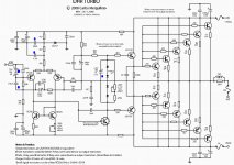
Some friends are asking me part lists or bom to the DHR Turbo
We have no boom, the thread and the schematic provides the needed informations that will allow the one to build.
Electrolitic condenser voltages are the same or bigger than the rail voltage, exception is the bootstrapp condenser that use to be rail to rail voltage..into the schematic it is 220uf to 100 volts.
Capacitors are for 100 volts... the blue ones you will see into the schematic attached, can be reduced voltage ones... alike 12 volts or other small voltage.
Resistances are 1/4 watt or 1/2 watt (250mW or 500mW) units...the ones are bigger have received other watt ratings printed into the schematic.
Zener is 1 watt...and read the whole thread before assemble..better to take a look at Greg pages too.
Dx amplifier is a simple amplifier, with a well know topologie, proved and approved by several factories that have used along this last 40 years..there's nothing special on it, only nice warm sonics. low measured and audible distortions, and reliability.
regards,
Carlos
Attachments
For the diode string can I use the BD139 and solder the 2 legs together or what can I use.I use Alex PCB
I do not understand what you mean
try to explain using other words, or draw by hand a sketch, try a schematic.
regards,
Carlos
try to explain using other words, or draw by hand a sketch, try a schematic.
regards,
Carlos
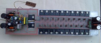
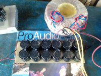
9 pair turbo
dear sir
greetings and wishes for a happy new year posting some pictures
of 9 pair turbo .Hand wound torridal transformer 50 60 70 o 50 60 70
tappings . condenser bank 60000 uf per rail
thanking you
andrew lebon
busy making dx blameless
dear sir
greetings and wishes for a happy new year posting some pictures
of 9 pair turbo .Hand wound torridal transformer 50 60 70 o 50 60 70
tappings . condenser bank 60000 uf per rail
thanking you
andrew lebon
busy making dx blameless
Attachments

![P1446[01]_22-12-09.jpg](/community/data/attachments/153/153822-f960aa2237d5f4d86d95beac9d920960.jpg?hash=-WCqIjfV9N)
Thank you Andrewlebon, nice work
About the Dx Blame ES, i would suggest you to stop for a while, there are folks int he Brazilian Audiophile Orkut Communitty building, and several boards are beeing tried.
Wait a little bit, i have asked them to test boards for me and three friends already moving to do that... some days more i will publish results about.
The amplifier sounds beautifull, but it is strange, sometimes unstable, i have lost some transistors while building the prototype, finally i have ONE stable.
So, better to wait, or to continue under your own risk.
About sonics it is unbeatable, lovely amplifier, if not the best audio amplifier ever made, may be one of them...BUT....i am not entirelly confortable with the unit.
................................
My dear friend Meanman
We have used transistors in the place of diodes to produce the needed voltage to bias the output... those are transistors connected as diodes, to sense the heat and control the stand by current....that will, as a consequence have some effects when the amplifier will be operating full power.
regards,
Carlos
Hi ,
meanman1964 have you sugest this
Happy new year !
Yes that's it Alex
- Status
- Not open for further replies.
- Home
- Amplifiers
- Solid State
- This is the DHR.... Dx High Resolution Turbo