This depends the capacitor position, it can increase gain for instance
also can send audio to ground and you will not have output audio, can overheat your amplifier (that zobel capacitor), and the bypass ones will overheat, will burn and the circuit will not operate correctly, fuses may burn because of them, well, short is a short!...each one of them will have a different result.
Capacitors does not read resistance, it is too high to be readed.
Electrolitic condensers, depending the value may charge or discharge througth your analog multimeter and you see the pointer goes up or down, depending the case or polarity.... the electrolitic condenser may have some leakage, but it is bigger thatn 10K, and this is not a problem.
Of course i will not describe what gonna happens pointing one by one, i have a pizza to eat!
ahahahahas!
Carlos
Last edited:
Power measurement, amplifier power, well, i think we can make mistakes
And i am, or i was, the master of mistakes Masterinvi.
The multimeters, the digital ones, have precision only if you are measuring sinusoidal waveshape and 60 hertz, your mains frequency....out from this frequency range, 40 to 200 hertz, the meter is not precise.
So, to measure power, first you need a load and a sinusoidal low distortion generator entering the amplifier input terminals, also you need an Oscilloscope to watch when the amplifier starts to clip, of course you may perceive the sonic differences using your ears. but when ears detect, the scope have already detected earlier and your detection is really a square wave, not the clipping threshold but much more clipped than the level we use to measure that is a very small clipping.
Measuring music playing, well, frequencies are not sinus, the frequencies are not the ones your meter can measure with precision...also if you evaluate sound with a speaker itself, outside the enclosure, it will not play loud or impressive, even if the unit is almost hitting the back end you will feel it is not strong.
The DHR turbo was made to dissipate enormous power in the load, not in the heatsinks, as it is not a Class A amplifier, when iddle it is dead cold, will be very hot when the heatsink is too small of if your power output is very high, also if you stand by current is wrong and too much high, i repeat, better to check 1 miliampere each power transistor, of course you can go to 15 miliamperes, but this means more heat together more waste of power and i doubt the advantage of it. The DHR turbo was made to power, audio quality was secondary, was an accident that also the audio quality resulted good, the target was power!
It can be transformed into a killing beast if you increase the driver's transistors iddle current to 40 miliamperes, but they must be into the main heatsink and you must reduce the floating emitter resistance a lot.... a killing beast, so killing that may be able to kill itself.
Using scope you measure the peak voltage and 70 percent of this may be your rms output voltage.... them multiply by itself (squared) and divide by your speaker impedance.... yes, you know that, but some reader does not know.
For instance, you read 8 volts...then multiply 8 volts by itself, means 64 as result, then divide by the speaker impedance, let's say 8 ohms, result is 8 watts.
When we measure using analogic meters, well, we have balistics, the pointer weigth, the measurement use not to be very good, we need stand sinusoidal signal and the frequency must be the one your meter has precision.
This amplifier, even with bad supplies must go to 150 watts, not 30 watts, so you really have problems, or your measurement method is not fine..but there are other possibilities, for instance:
Transformers that use bimetal inside the secondary or primary coil, they do that for protection, bimetal when over heated switch off the circuit, a thermal protection, but, sometimes this shows enormous series resistances that kills the transformer output voltage stability, reduces a lot the transformer power because of series resistance...these transformers, or other defective transformers, have enormous drop of voltage when you suck energy from them.
Check, dear Masterinvi, the voltage you have when your amplifier will be producing 30 watts you said, also inform your load, your measurement method and your supply voltage under load conditions and without load.
There's no possible magic, power amplifier produces audio power if the supply can manage to send power to the amplifier, weak supplies will never produce high power, we need huge transformers, squared monster measuring 20 centimeters each side if E/I type to obtain 600 to 1 Kilowatt of power in a single channel... a lot of transistors cannot do that, we need huge electrolitic condensers filtering and enormous transformers, and the transformer power must be, at least, 60 percent bigger than your expected output power, say, to 1 Kilowatt of audio you nead 1.6 Kilowatt transformer. (Class AB)
regards,
Carlos
Last edited:
uncle carlos,
500mv across 1ohm emmiter resistance at output transistor if dxturbo is playing, is it okey?
Also 1.5 volts at Point A to Point B while playing, Is it okey ? when amp is in idle its 2 volts.
Output seems to be hotter compared to my Dx Amp. Only 8 Ohms load i tried today.
Regards
500mv across 1ohm emmiter resistance at output transistor if dxturbo is playing, is it okey?
Also 1.5 volts at Point A to Point B while playing, Is it okey ? when amp is in idle its 2 volts.
Output seems to be hotter compared to my Dx Amp. Only 8 Ohms load i tried today.
Regards
No!, 500 milivolts means 500 miliamperes, it is 5 hundred times bigger than the
correct current.
You have errors, 1.5 volts of bias measure from colector to emitter VBE multiplier cannot result all that enormous current to each power transistor, this is an assassination, the power transistors will but and very soon.
Are you kidding Masterinvi?, i said 1 milivolt, not 500 milivolts!
The current is the voltage reading over the emitter resistance, expressed in Volts (0.5V) divided by the resistance value (1 ohm), so you're having 500 miliamperes.
Measurements are made with the amplifier in iddle mode, without audio entering, in stand by mode.
Man!, you're not prepared to build power amplifiers, maybe you are good for television.
regards,
Carlos
Last edited:
yeah thats what im thinking also,
i will just try my best, if i have successfully build your dx amp maybe i will succeed also in this one, i try my luck.
thanks for being generous uncle carlos...
i will just try my best, if i have successfully build your dx amp maybe i will succeed also in this one, i try my luck.
thanks for being generous uncle carlos...
Sorry, i have lost patience with you, i was shocked and deeply scandalized with these
500 milivolts.
Well, 50 milivolts is still a very high current. as this means 0.050V divided by 1 ohms, this is 50 miliamperes crossing each power transistor..it is too much, fifty times what i have suggested, and 5 times the highest value you usually find in amplifiers.
Power is the current multiplied by the voltage, you see, each transistor will have around 80 volts from your supply, this will be the voltage you can measure from colector to emitter, say, one probe tip at the colector and the other one at the emitter, and 50 miliamperes will be crossing (80 X 0.05 = 4 watts)
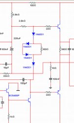
This is too much, try to reduce and continue to check your amplifier, voltage measured from the NPN driver base to the PNP driver base must be 2.1 volts or higher, or your emitter floating resistance is wrong or you have other mistake, this 2.1 volts should be distributed to drivers and output transistors base to emitter junctions, and these voltages, around 520 milivolts should appear at the drivers base to emitter and also at the output base to emitter junctions, if you have, for instance, 400 milivolts at your driver, and 650 milivolts at your output base to emitter junctions, then you have wrong floating emitter resistance value.... voltage must be divided by driver and power transistors in a fair way, not too much for one and small voltage for other... check that.
Reduce your current to read 1 to 5 milivolts to each one of your power emitter resistances, no audio entering..... no possible?, then check your circuit and transistors because you have errors, mistakes, human failures, wrong parts ro damaged parts.
regards,
Carlos
500 milivolts.
Well, 50 milivolts is still a very high current. as this means 0.050V divided by 1 ohms, this is 50 miliamperes crossing each power transistor..it is too much, fifty times what i have suggested, and 5 times the highest value you usually find in amplifiers.
Power is the current multiplied by the voltage, you see, each transistor will have around 80 volts from your supply, this will be the voltage you can measure from colector to emitter, say, one probe tip at the colector and the other one at the emitter, and 50 miliamperes will be crossing (80 X 0.05 = 4 watts)
This is too much, try to reduce and continue to check your amplifier, voltage measured from the NPN driver base to the PNP driver base must be 2.1 volts or higher, or your emitter floating resistance is wrong or you have other mistake, this 2.1 volts should be distributed to drivers and output transistors base to emitter junctions, and these voltages, around 520 milivolts should appear at the drivers base to emitter and also at the output base to emitter junctions, if you have, for instance, 400 milivolts at your driver, and 650 milivolts at your output base to emitter junctions, then you have wrong floating emitter resistance value.... voltage must be divided by driver and power transistors in a fair way, not too much for one and small voltage for other... check that.
Reduce your current to read 1 to 5 milivolts to each one of your power emitter resistances, no audio entering..... no possible?, then check your circuit and transistors because you have errors, mistakes, human failures, wrong parts ro damaged parts.
regards,
Carlos
hello Masterinvi!
have exploded?
this is always a possibility
YouTube - Dx Hammer-Turbo, big storm!
eregards,
Carlos
have exploded?
this is always a possibility
YouTube - Dx Hammer-Turbo, big storm!
eregards,
Carlos
No, i just keep it playing in my shop with only 1 pair of output (2SA1106 and 2SC5198), using 50 vdc supply, 8 ohms load and volume control at 30% only. Seems fine. Cant turn full the volume, my 80 watts speaker seems to explode.
I have to test it with high wattage speakers tommorrow. and 70 vdc supply.
all voltages in all test points are in normal.
I install 681 mylar capacitor between base and collector of input transistor(2N5401) because there is pot! pot! pot! sounds in speaker even no audio, seems like oscillation. Lot of mistakes in my construction, My fault. after installing the caps pot pot pot gone.
Amp plays fine and clear, bass cant be feel because the speaker is not in the enclosure(just a test)
To test tommorow at full power with huge speakers.....
Last edited:
Ahahahahah!, motor boating... there's a very long time i do not listen this
Some rail condensers are missed, defective or inverted, motor boating is always because of condensers.
enjoy your amplifier that came together with a boat and a motor!
regards,
Carlos
Some rail condensers are missed, defective or inverted, motor boating is always because of condensers.
enjoy your amplifier that came together with a boat and a motor!
regards,
Carlos
yeah i dont have output rail capacitor(those 1000uf 100v), but i have input rail capacitor but its only 470 uf 160v( taken from television set). I just dont beleive that without them amplifier will not operate or amplifier will explode. Maybe im wrong.
Of course i will install them (rail capacitors) as soon as the amp will normal.
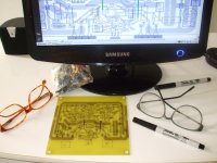
Same as my DX AMP i construct this amp from scrap. Not same with pics posted here that all parts are new. I dont know, I just love to recycle.
Even the trimpots are from television set, those use to control subbright vertical hold etc etc... I just look the resistance, if same with specs of dx turbo i remove it and install in the amp.
My shop is full of scrap, junk television boards.
My PSU filter capacitor is 10000uf 80V, they are new, my friend give it to me.
Of course i will install them (rail capacitors) as soon as the amp will normal.
Same as my DX AMP i construct this amp from scrap. Not same with pics posted here that all parts are new. I dont know, I just love to recycle.
Even the trimpots are from television set, those use to control subbright vertical hold etc etc... I just look the resistance, if same with specs of dx turbo i remove it and install in the amp.
My shop is full of scrap, junk television boards.
My PSU filter capacitor is 10000uf 80V, they are new, my friend give it to me.
An externally hosted image should be here but it was not working when we last tested it.
Last edited:
I do not believe too, but motor boating is always a result of electrolitic condenser
with defect, wrong capacitance, leakage, defective, misplaced, forgot, absent, inverted or soldered wrong place... of course associated resistances produces the "time constant" of charge discharge, and this charge and discharge is the motor boat, or produces the motor boat sound when transistors sense this.
Also capacitors do that, but usually happens a time constant of charge and discharge of capacitors that produces the popping sound, sometimes transistors goes on and off producing the noise, but ALWAYS the cause is absence of capacitor, or condenser, or electrolitic condensers, or they are missed, or damaged, or inverted,misplaced, forgotten or something connected to capacitance.
If you show me another part doing that, bring to me and i will eat the part and will produce a picture doing that to publish my shame.
Of course, a wrong rail resistance, in the place to be 100 ohms and people installed 10K, may produce something strange because will charge CAPACITORS in a very slow way that will produce some noises from time to time..... time constant is capacitor associated with resistance, one of them is wrong.
Now you "just don't believe", so, you are becoming better, as you have some beliefs.
Yeah, dear brother, i do use junk too..i love junk, they are tested parts, senior parts, guaranteed components.
Not the PSU condensers, search for the rail condensers, the ones after the rail series resistances, and check if other capacitors or condensers are misplaced, or if they have wrong value of resistances associated with them.
regards,
Carlos
Attachments
Last edited:
when i get home i check again the diagram from gregs webpage to see if there is capacitor between base to collector of input transistor, but nothing is there.
i have to recheck the electrolitic caps in my amp tommorow using my ESR again, i check them before i fix them in board. Maybe they became leaky as im working with this amp. So i have to recheck them.
Amp is happily playing for about 5 hours with 1 pair of output at 8 ohms speaker.
But with capacitor from base to collector of input transistor.
Enjoy, your amplifier has a broken leg and a hand missed, maybe
using Wheeled chair but it is alive.
Enjoy.
regards,
Carlos
using Wheeled chair but it is alive.
Enjoy.
regards,
Carlos
i hate baseless presumption, i love theory from facts and evidence. I love science.
Thats why i love to ask you and get knowledge from you, i know you start from being nothing from your brain.
Just a question, is high voltage rating ciramic or mylar capacitor affects the sonic or stability or behavior of the amplifier? I ask because the 100N capacitor i fix in parallel with 470UF 160 volts rail condenser(the one in series with rail series resistance) explode as i power up the amp for the first time. So i change it with same capacitance value but with voltage rating of 2KV( i salvage the capacitor from Main Supply Voltage of television circuit).
So i change all capacitor( those with Nano and Pico farad values) with 2KV voltage rating) I cant find rating 100 volts only or slightly bigger. Thats all i found.
Regards
I don't know, i will have to think about, this never happened to me
so...it is very strange thing.
If you were in my place, my culture, i would say the equipment deserves some smoke from cigar, some drums to keep bad spirits distant and some prays...ahahahahaha!
But as you are from other culture, i would try some scientific approach, as soon as i understand what happened.
regards,
Carlos
Maybe a mistake...i am not sure...
but if your capacitorvwas 100 Volts, and by accident you have connected that unit form rail to rail....them 140 to 160 volts may result in a explosion.
I never had exploded capacitors, so, i am not very skilled about....you may know more than me, as you work with tv sets, and they operate with high voltage, so, you may face some explosions from time to time.
regards,
Carlos
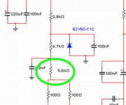
changing the caps value of zobel network from 470 picofarad to 470000 picofarad eliminates the motor boating. My fault, very small markings on the caps makes me think that its 474 when actually its 471.
High voltage caps blue color lots of letters and numbers. needs magnifying glass to read.
have not tried in big speaker today, lots of unit to repair. maybe tommorow.
High voltage caps blue color lots of letters and numbers. needs magnifying glass to read.
have not tried in big speaker today, lots of unit to repair. maybe tommorow.
- Status
- Not open for further replies.
- Home
- Amplifiers
- Solid State
- This is the DHR.... Dx High Resolution Turbo