George, I have a home-made tool for inserting wires into the T30 terminals easily, without getting sore fingers:
If you want one, message me with an address. It's made from a soda straw size stainless steel tube using a thin grinding disk.


If you want one, message me with an address. It's made from a soda straw size stainless steel tube using a thin grinding disk.
I was thinking something like these Mini Grips ( vertical Fahnestock pins ) until you just posted the spring button things. These Mini Grips are $0.60 each on an Ebay site, like 6X the price of the T30 terminals.Currently I use vertical spring clips that accept up to 14 gauge wire
I haven't fully decided exactly what I want to build yet, so I may or may not use the T30s in it. The T30s look like it would be far too easy to break, or rip them right off the board. Plate through holes with large annular rings would work, but I'm making one off's that may be hand wired on perf board so something more substantial might be a good idea. I ordered some of Windcrest77's green and orange connectors from two different places at two very different prices, but both are direct ship from China with delivery dates 2 to 3 weeks out.
I gave up on tube testers back when I figured out that they had a significant number of false positives and false negatives. I will test them in a mock up of the circuit that I intend to use them in. That accomplishes two things. I have a sample of tubes from both ends of the spectrum and in between to pick my "test tubes" from, and I'll learn how my circuit responds to all sorts of tubes across that spectrum. Sometimes it means fixing the circuit and testing the batch of tubes again.
When I was a kid tinkering with tubes two places that I always rode my bike to were the trash bins behind the two TV repair shops near my house. There were always tubes in their trash and many of them worked fine in my experiments. Those that didn't work met my "power supply." What does a kid in the 60's use for powering tube stuff? I had a big Lionel Train transformer that put out a bunch of current. "Slow" was about 6 VAC. "Fast" was about 18 volts and there was an infinite number of speeds in between thanks to a brush system like that found in a Variac. I fed that into the heater windings of a monster transformer that I got somewhere, but it was far too big to have come from a TV set. That fed a couple 5U4's and some caps. The trash can tubes that didn't work just got melted, unless they were too dead to blow up. Fast forward to high school and while my friends were flipping burgers or pumping gas (self service gas stations were not yet invented), I was fixing TV's at one of those shops.
I spent quite a bit of time using an original TSE board to test WE417's and 5842's back in the mid 2000's. These old high GM tubes are indeed all over the place spec wise. And, yes, from my limited experience the WE 417's tested and sounded better than the Raytheon 5842's. Once I have the pentode gain stage working, I will run a lot of different tubes through it for both parametric testing and listening tests. Even some of these newer production TV IF amp tubes are also all over the place spec wise.
How do think I wound up with almost 100,000 tubes and a mountain of unfinished projects. Moving everything 1200 miles cut down the mess by about 80%.I need to tinker but within limits of the chosen topology I want to study or knowing me my ADHD will have me chasing every shiny object in any tube book and I spin my wheels.
I gave up on tube testers back when I figured out that they had a significant number of false positives and false negatives. I will test them in a mock up of the circuit that I intend to use them in. That accomplishes two things. I have a sample of tubes from both ends of the spectrum and in between to pick my "test tubes" from, and I'll learn how my circuit responds to all sorts of tubes across that spectrum. Sometimes it means fixing the circuit and testing the batch of tubes again.
When I was a kid tinkering with tubes two places that I always rode my bike to were the trash bins behind the two TV repair shops near my house. There were always tubes in their trash and many of them worked fine in my experiments. Those that didn't work met my "power supply." What does a kid in the 60's use for powering tube stuff? I had a big Lionel Train transformer that put out a bunch of current. "Slow" was about 6 VAC. "Fast" was about 18 volts and there was an infinite number of speeds in between thanks to a brush system like that found in a Variac. I fed that into the heater windings of a monster transformer that I got somewhere, but it was far too big to have come from a TV set. That fed a couple 5U4's and some caps. The trash can tubes that didn't work just got melted, unless they were too dead to blow up. Fast forward to high school and while my friends were flipping burgers or pumping gas (self service gas stations were not yet invented), I was fixing TV's at one of those shops.
I spent quite a bit of time using an original TSE board to test WE417's and 5842's back in the mid 2000's. These old high GM tubes are indeed all over the place spec wise. And, yes, from my limited experience the WE 417's tested and sounded better than the Raytheon 5842's. Once I have the pentode gain stage working, I will run a lot of different tubes through it for both parametric testing and listening tests. Even some of these newer production TV IF amp tubes are also all over the place spec wise.
When using these vertical clips, I keep a small blade screwdriver handy to press down the spring levers, the levers have a slot that fits a tiny screwdriver just press and insert the part(s).
Back when I 1st got the T30 terminals, I was also looking at a scheme more closely related to their intended usage. They can be driven into a 3/32" hole in firm wood or plexiglass. One would just drill a terminal hole pattern around the tube socket (surface mount easiest), drive the pins in with a hammer, and connect (solder) small flexible wires between the tube socket pins and the terminal bases (just below the spring ). That would firm up the pins.
The spring depressor tool works quite well, by the way. No more sore fingers. Only took me a half hour to make a half dozen. Let me know if you want one. Vector made a similar tool with a nice wood handle, but I can't find one online.
The spring depressor tool works quite well, by the way. No more sore fingers. Only took me a half hour to make a half dozen. Let me know if you want one. Vector made a similar tool with a nice wood handle, but I can't find one online.
Last edited:
We all have our "Big Brother is watching us" theories and some of them may be true especially when it comes to internet use, but here is some more fuel for the fire. Google decides what to put in front of me every time I open up YouTube. My YouTube viewing spans a wide gamut of totally unrelated stuff from classic rock music videos to automobile racing, rock and other climbing or hiking videos, electronics from tube amps to modern microcontrollers and maker boards, woodworking and guitar building, to weather and current legal issues, and I occasionally watch the Miami TV channel news, so they have a lot to guess from. Today I get this:

I wish they put more variety - which I know they have - in front of me. SOS repeating; it seems to the point of almost goading me to watch it.Google decides what to put in front of me every time I open up YouTube.
Makes me wonder if there's a hack for that.
Sometimes I even open up a "private" instance of the browser, to get a more generic content feed other than dictated by my recent cookies.
They should offer "entropy" controls in different dimensions. Like, give me more "wild" picks along the dimension of time. Give me an older / newer slider that I can slam to the extremes. Or music - you know what I like; how many times you going to suggest the same CSNY show - what, until I finally watch the damn thing? Give me an entropy control on that dimension to stir things up if I want.
I dont know who they have programming the UI, but it seems they've no imagination. As-is, half the time I simply realize I'm wasting my time on it.
I counted 60 pin select relays on 10 of the 20 PC boards. With all those computer controlled Voltages and metering, where is the curve trace output?
I just use a Pomona Test adapter socket and clip on wires. Look inside the tube to see what pin is what function.
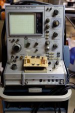
Here is the (2nd) $400 curve tracer I got for parts recently. (turned out so easy to fix, I'm using it for tube or SS testing now) (camera shutter timing caused the blanked traces ) Notice the Pomona Test adapter holding the tube at lower right. Or could use surface mount sockets too.


I just use a Pomona Test adapter socket and clip on wires. Look inside the tube to see what pin is what function.
Here is the (2nd) $400 curve tracer I got for parts recently. (turned out so easy to fix, I'm using it for tube or SS testing now) (camera shutter timing caused the blanked traces ) Notice the Pomona Test adapter holding the tube at lower right. Or could use surface mount sockets too.
Last edited:
Youtube is great, the wife and I rarely watch TV anymore except to see a movie on a big screen. The trick to get the content you want pushed to you on youtube is mostly based on what channels you subscribe to. Like George I subscribe to a range of interests, all the subjects he mentioned, but I'm a history buff too youtube is amazing for history in any manner. Once you get over 100 or so channel subscriptions on your account, youtube does an amazing job of enriching your mind with knowledge. I feel sorry for folks who think Facebook and TikTok are their only uses for a computer. They are not being enriched intellectually, a constant stream of memes does not educate you, it probably just indoctrinates you. Grown men IMO don't belong on Facebook myself, it reads like a giant fashion magazine.
I did get this other tube tester video pushed to me too, nice.
I did get this other tube tester video pushed to me too, nice.
wonderful, that's how we used to work and test stuff back when I was studying.Notice the Pomona Test adapter holding the tube at lower right.
These days probably wouldn't be allowed anymore lol
I had a teacher plugin in banana jacks directly into the wall socket (same size here in EU) to show a certain experiment.
With the wise words; "Don't do this at home kids, and you've never seen me doing this" 😀 😀
Definitely NOT OSHA approved with all those "hot" pins sticking out. And I've tested them a few times. Do Not touch the RED lead! I actually modded the curve tracer so that it's highest plate V scale (1500V) is now "just" 750V. Sleeping better at night.
There must be a few Tubies out there with Tek 576 Curve Tracers. I see the 10X Grid Step Amplifier modules (for tube curve tracing using the Tek 576, -200V max step range) have sold out. Hopefully they get some more in. Working nice.
https://www.ebay.com/itm/266682053587


I have an assortment of medically approved isolation Xfmrs for those "Un-Approved" kind of tests.plugin in banana jacks directly into the wall socket
There must be a few Tubies out there with Tek 576 Curve Tracers. I see the 10X Grid Step Amplifier modules (for tube curve tracing using the Tek 576, -200V max step range) have sold out. Hopefully they get some more in. Working nice.
https://www.ebay.com/itm/266682053587
Last edited:
I should mention that I use a 750 Watt Medical Isolation Xfmr to power the Tek 576 Curve Tracer. Plastic knobs on the tracer of course. At least -some- safety factor with that. The Tek 576 is rated 305 Watts max. The HV supply is rated 220 Watts. I should wrap some electrical tape around the unnecessarily exposed outer test socket pins. Most shocks have been from one finger to the next.
The tube socket adapter Ebay shows with the Step Amplifier (in the pic above) is nicely insulated, however, you can only get one tube plugged into it. The tracer can do two tubes, using the big toggle switch, for comparing/matching tubes. So this adapter is not that desirable. My (dangerous) Pomona socket adapter scheme allows two tubes to be connected up simultaneously, and I have Pomona adapters for 7, 8, 9 pin, Novar, Compactron, Loctal, Magnoval and even sub-mini tubes.

The tube socket adapter Ebay shows with the Step Amplifier (in the pic above) is nicely insulated, however, you can only get one tube plugged into it. The tracer can do two tubes, using the big toggle switch, for comparing/matching tubes. So this adapter is not that desirable. My (dangerous) Pomona socket adapter scheme allows two tubes to be connected up simultaneously, and I have Pomona adapters for 7, 8, 9 pin, Novar, Compactron, Loctal, Magnoval and even sub-mini tubes.
Last edited:
I have two different pairs of snub nosed pliers (like a sawed off needle nose) that work well for stuffing wires into the T30s.The spring depressor tool works quite well, by the way. No more sore fingers. Only took me a half hour to make a half dozen. Let me know if you want one. Vector made a similar tool with a nice wood handle, but I can't find one online.
Adapter, we don't need no stinkin adapter.......Notice the Pomona Test adapter holding the tube at lower right. Or could use surface mount sockets too.
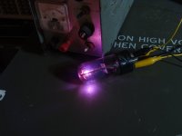
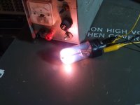
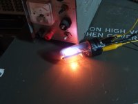
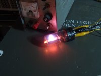
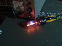
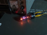
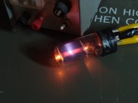
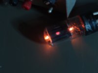
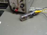
I found this 1943 vintage TV damper tube in a box full of used tubes that probably came from a hamfest. There was a hole burned clean through the plate making the cathode visible. I fired it up on a pair of power supplies to find that it still bettered the published curves for voltage drop VS forward current. I did not trust it, so I decided to take the test a little bit beyond the published values and the rated maximums. This tube put up a good fight. It took me about an hour to kill it. Death came when the blue ray that was shooting out of the hole turned into a plasma followed by arcing and particles of vaporized cathode began impacting the glass eventually leading to a crack. The first picture is after the long cooldown.
Attachments
-
 DSC00100.JPG591.9 KB · Views: 84
 -
 DSC00092.JPG273 KB · Views: 90
 -
 DSC00091.JPG364 KB · Views: 76
 -
 DSC00088.JPG344.4 KB · Views: 69
 -
 DSC00082.JPG331 KB · Views: 77
 -
 DSC00081.JPG320.6 KB · Views: 81
 -
 DSC00077.JPG320.2 KB · Views: 71
 -
 DSC00074.JPG313.7 KB · Views: 79
 -
 DSC00069.JPG174.5 KB · Views: 79
 -
 DSC00095.JPG372.9 KB · Views: 80
Maybe I should send George my defunct tubes for a proper disposal.
I got my 2x "snap-in" 9 pin tube sockets today. I promptly went over to Lowes Hdwr to find some PVC end cap it would fit into for mounting. I found that a 3/4" Lasco PVC Plug fits perfectly, but not enough socket pin over-hang is available to solder any kind of terminals to it. Pic below. Won't work for a surface mount socket. Tossed it into my almost over-flowing "useless junk" bin. That metal shield contact thingy sticking up looks like it's even giving me the finger. Where's that sledge hammer? These snap-in / push-in sockets are banned. I tried.

I got my 2x "snap-in" 9 pin tube sockets today. I promptly went over to Lowes Hdwr to find some PVC end cap it would fit into for mounting. I found that a 3/4" Lasco PVC Plug fits perfectly, but not enough socket pin over-hang is available to solder any kind of terminals to it. Pic below. Won't work for a surface mount socket. Tossed it into my almost over-flowing "useless junk" bin. That metal shield contact thingy sticking up looks like it's even giving me the finger. Where's that sledge hammer? These snap-in / push-in sockets are banned. I tried.
Last edited:
Doesnt other stuff come out within such rays, like Xrays perhaps?Death came when the blue ray that was shooting out of the hole
Recalling a couple of things from childhood; my fathers GE color TV had some printed warning near this capped tube (that could only be a diode) pasted to its metal cage about Xrays. Then my own fantasy about making a particle beam weapon out of an old TV CRT gun...which never made it past how I'd put back the vacuum or design a new anode for it.
If you lived next door instead of the "other TV repair guy" who'd never do such things, the above experiment would have given me a lot of hope for achieving that ;')
Last edited:
Generating X-rays takes a lot of voltage. The X-ray machine we had at Motorola was a baby by medical standards and the HV knob started at 75 KV and went to 150 KV.
There were two capped tubes in the HV box in a late 60's vintage color TV, the HV rectifier usually a 3A3A, and the regulator. The older 25 inch color TV's used a 6BK4 high voltage shunt regulator tube that ran with 24 to 27 KV across it. They DID produce some X-rays. Once these were discovered, newer generation shunt regulator tubes used leaded glass and angled plates to keep most of the X-rays inside the tube. A new generation of "beam triode regulator" tubes like the 6JD5 were developed in the early 70's that worked on the primary side of the flyback transformer instead of the secondary for lower voltage operation. Even in the 3 to 5 KV range no X-rays were generated.
The 6AX4GT seen in my picture never saw more than about 100 volts. With about 100 volts it would have been passing over 1 amp and dissipating over 100 watts against a 5.5 watt rating for a short unhappy life.
Generally speaking. in the most favourable conditions for meaningful X-ray production, I would say that 10KV is about the minimum voltage. However such "low" voltage X-ray power supply will make the X-ray generator inefficient (likely small fraction of 1%) and won't have much practical use. Most generators use medium-to-high atomic number targets like tungsten and molybdenum and that means that an efficient X-ray production will only be achieved with rather high voltages > 70 KV. In fact the presence of K emission line of the Tungsten in the Bremsstrahlung radiation makes it a lot more efficient and requires minimum 90-100 KV normally to be efficient. That line (single energy) alone can contribute up to 25% of total amount of X-rays produced. These target materials, that can be the plate or are embedded in the plate, are also required for their high melting point and useful heath dissipation as only a small percentage of the energy is turned into X-rays while most of it will be heath. Much less efficient the class A tube amps! Otherwise one will see things like copper rotating anodes, with or without embedded targets, where the fast rotation has precisely the function of heath dissipation. The typical copper rotating anode generator runs with at least 40 KV but the excitation potential is 8 KV "only".
@jjasniew build yourself a table-top synchrotron!😀 Just joking....
@jjasniew build yourself a table-top synchrotron!😀 Just joking....
Last edited:
Just dug out from under the AVALANCHE of TUBES from this morning. ( NJ Earthquake! ) We WILL re-stack!!
( April Fools! )
( April Fools! )
Last edited:
Same thing here -- when I blew the transformer in the power supply for my ham transceiver, a local TV-repair guy gave me a replacement (he was also a ham). But it was from his "stash" of mil surplus. If I recall, the transformers for those early color TV's were real beasts.When I was a kid tinkering with tubes two places that I always rode my bike to were the trash bins behind the two TV repair shops near my house. There were always tubes in their trash and many of them worked fine in my experiments. Those that didn't work met my "power supply." What does a kid in the 60's use for powering tube stuff?
I have used the 576 for tubes -- was able to purchase surplus plug-in adapter not yet changed over to tubes.
Thanks for posting the Youtube video. It was interesting.
Attachments

My father had some B&W TV within a big Bakelite enclosure. The PT had fins as in some of the laminates were extended to make fins like on a heatsink. Never seen another one like it.If I recall, the transformers for those early color TV's were real beasts.
"The PT had fins as in some of the laminates were extended to make fins like on a heatsink. Never seen another one like it."
I remember a few like that from the 1960s. They were dipped in some sort of thick dull black paint after assembly which made taking them apart nearly impossible. The hammer revealed that those extra wide laminations were exactly that. There were 5 or 6 extra large lams inserted into the core stack every 1/4 inch or so.
In the late 60's I was building solid state amps from magazine plans. The transistors could be ordered from a large distributor that catered to the TV repair shops, but transformers to power these creations were unobtainable without buying the whole kit, and wiring a box full of Radio Shack or Lafayette Radio Electronics filament transformers together was not economical for anything beyond 5 to 10 WPC. I would take the covers off a tube TV transformer to see if the primary was the first winding put on the cardboard core. It usually was. If this was the case, I ripped off every outer winding and wound a new secondary. Simple math and a careful turns count of the 5.0 and 6.3 volt windings provided the needed info for the correct number of secondary turns.
They weren't common, but some older TVs had the 5U4 socket mounted right on the power transformer. I dug into a big TV in the trash dump one day to find a power transformer with TWO 5U4 sockets on it. I kept that big boy until I left home at age 20.
- Home
- Amplifiers
- Tubes / Valves
- This guy is doing this hobby the way I always wanted to do it