It was interesting the thing he did with the two triangle waves on the scope, then moved over to the analyzer to fine tune into the nice cascade of harmonics that suppressed the third harmonic, which was initially dominating the whole profile.
What exactly was he doing with the two triangle waves? And how to hook it up? Was one wave simply the signal at input and the other at the output of the tube? What was he adjusting to be satisfied with the triangle waves, level, grid v, plate v, screen v, plate and cathode resistors?
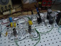
The amazing thing about his whole setup is that he has variability of all aspects at his fingertips. Circuits can be the art of compromising, being able to dial in and make the compromises you want in real time is priceless it seems to me.
What exactly was he doing with the two triangle waves? And how to hook it up? Was one wave simply the signal at input and the other at the output of the tube? What was he adjusting to be satisfied with the triangle waves, level, grid v, plate v, screen v, plate and cathode resistors?
The amazing thing about his whole setup is that he has variability of all aspects at his fingertips. Circuits can be the art of compromising, being able to dial in and make the compromises you want in real time is priceless it seems to me.
Cheap function generator.
Those use diodes to non-linearly shape the triangle into a sine-like waveform.
But the distortion is rather high.
Was one wave simply the signal at input and the other at the output of the tube? What was he adjusting to be satisfied with the triangle waves, level, grid v, plate v, screen v, plate and cathode resistors?
He adjusted the tube's operating point for the best triangle wave output.
It helps to compare the output with the input to see the differences, and how linear the ramp of the triangle is.
The best point is amplitude dependent, but the distortion reduces with reduced amplitude.

Assuming it was a common-cathode stage he was adjusting, there must be an inversion somewhere to get the triangles to match. Scopes typically have a knob to turn the curve upside down, otherwise you need an extra inverting amplifier. You also need to correct for the gain somewhere.
A few years ago I built a similar but simplified tube tester. It is made out of nothing and it can test only the most common types of small signal double triodes. I need to have the datasheet on hand and then verify if the tube is anywhere around the specs and if the two halves are matched. It can test at a few different operating points so I call it kind of "dynamic matching" within its limitations. With a lot of patience it can serve as a manual curve tracer as well. I always wanted to add signal output like the one discussed here. I might return to this some day.
Attachments
I found another nice tube testing video, which for my purposes would be to begin to design a "tube lab" device to eventually set the operating points, listen to sound, tweek into a harmonic profile, etc. all experimentally. I'm thinking mine would have totally isolated B, screen and grid bias supplies, Maida and regulated, with current limiting adjustable. DC filament also variable, high current, I have a multitap low voltage transformer that would work for that. Then I'd have to add the ability to listen to the tube, and a way to real-time see the harmonic profile as I change operating parameters. Basically a universal educational tube lab.
Is there the possibility that adjusting the amplifiers distortion with a waveform at a fixed frequency, that the distortion may change at different frequencies?
It would be interesting to do a controlled switch between listening and an analysis. Like REW plays a tone file and does a spectral analysis, allowing you to arbitrarily adjust the tube operating parameters while looking at the spectrum. The tone is of course muted in this mode.
Then, push a button and a musical selections plays, the muting turns off. (Or your guitar's sound now comes through)
Go back n forth with that for a while (trying different tone files at various frequencies) Swap the order; adjust parameters using the music first, then look at the spectrum of what you thought sounded better.
Also the harmonic distortion profile of cascading stages probably matters too. A device that allows you to "dial in" an operating point that gets you just the right harmonic profile for a single tube is a cool device. But the following stage in the amp might be cancelling that or adding to it. After you get the first stage how you like it, I guess you can profile your next stage, then apply the first stage as the test signal to see how they interact. Designing to retain the harmonic profile you want is probably what I'm thinking, its just one of many goals you can prioritize I guess among, designing to power, tube life, CMRR, etc. Since the "magic" of tubes seems to emanate from its harmonic distortion profile it seems a good place to start. I did find software that gives the same kind of harmonics bar graph the man in the first video is using to set his ideal operating point, I just need time to learn it. Switching between hearing music, varying operating points and looking at the distortion profile changes easily to me is a unique kind of "tube lab" device, I've never seen before.
Follow-up video!
Love to find out where he was able to get the chassis and plug in boards, and a BOM !
Love to find out where he was able to get the chassis and plug in boards, and a BOM !
Thanks, he offered to record a video of his latest version and he did, I'll have to thank him. I see now how triangle waves are easier to match up than sine waves, its easier for a person to compare the point of a triangle than it is for a person to compare the minutely different slopes of two sine waves.
I like that his tester doesn't have every possible socket wired up pin to pin, you just make a module for each tube base you need. This means that you dont have to have all those long wires going to the sockets you're not using, which could cause oscillation. No need for complex switching, which could cause more oscillation. Using socket modules he can make a jumper that has a built in grid stopper if a tube is oscillating. He used a TL022 op amp as the output buffer to either a scope or his power amp or his audio analyzer. Any chip with a very high input impedance would be good here I suppose, so as to not load the anode of the DUT. For portability one can use a little headphone amp as the power amp, not needing a speaker and power amp. Meter can be digital if preferred, he has no anode voltage meter or grid voltmeter but used pin jacks to just plug in a couple of DMMs, nice, makes sense that only the series wired ma meter needs to be part of the device. He doesn't have any switches to turn off the B+ or grid, makes sense it's DC, you just have to unplug it when you want to see what your ideal cathode/anode resistors came out to be after dialing it all in. I seriously need to redirect my learning about tubes into this direction. This would also be a great post to link to from the "Tube Learning" sticky thread.
I cant get over it, he grabs a random tube, wires it, and after his procedure knows the optimal anode voltage, screen voltage, grid bias, K resistor and A resistor for how the tube sounded and to his preferred harmonics profile, all in about 10 minutes, very cool. Why would one need curve graphs to make a proven fine tube stage if you can do it with real tubes?
Is there anything others would add or change to such a device? For convenience, versatility, safety, stability, etc. Maybe we can co-design the DIYAUDIO tube learning device?
Last edited:
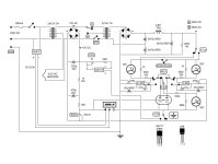
Ever see http://tubelab.com/articles/tubelab-prototyping-system ?
One would think you could have the cathode, anode control pots on a card, the input level control on a card, as well as the output buffer, the current meter. Perhaps instead of a signal generator / scope, use a quality USB soundcard and REW for signal generation / analysis. The input / output buffer design would also protect the - wimpy vs a tube - soundcard I/O.
The more difficult bits would be power supplies for plate and screen. For example, what would be sufficient for a 12AX7 analysis would not for a 6L6. Or - perhaps - the supply design good for 12AX7 would serve as well for just the screen of a power tube.
That's a nice approach to breadboarding, yes. Maybe power stages would have another tube tester tailored to that task, but still have the ease of wiring. The output is a transformer not an opamp buffer, so it's a different animal. I see two tube testers needed one for voltage tubes like the video and one for power tubes. The tube tester in the video might need a fourth position on the output selector. That position would connect the anode to a coupling cap or interstage then that would be followed by the power tube tester. Then you could flip the output to the power tester. Yes an opamp buffer is nice to not blow your soundcard.
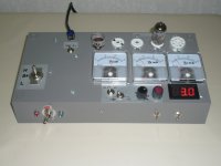
There have been several "tube labs" over the past 20 some years. All have been superseded by tubelab II or tubelab III or whatever since I always think up something better or different in some way. The "tube lab" has varied in purpose from something to test tubes and generate curves, to something that I can design amps on. I spent far too much time trying to build a better "tube lab" that it became my focus and in 2005, the name of my company. The picture in post #33 is of Tubelab III. It was not the third iteration, just the third one that I liked enough to use for an extended period of time. I used it to torture lots of different tubes in screen drive back in about 2005 - 2007. The amp on Tubelab III at the time of that picture is "screen drive 800." I have no idea of where that name came from except maybe the fact that it made 80 watts of power.
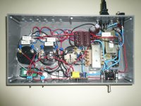
I found a picture that is zoomed in a bit more so that the writing is legible. There was a box full of modules. Each module fit one or more of the popular JEDEC tube base / pinouts. This amp used two that can handle 9A (12AX7 and similar) and 9AJ (6DJ8 6BQ7 etc) tubes and one that handled a pair of 6CK tubes (6AV5). Other modules held the individual components. This worked but having to screw down each wire, or bunch of wires took considerable time.
After 10 years of doing amp design on Tubelab III I got pretty good at just building an amp on perfboard and having it work well enough to start tweaking on so that the Tubelab prototyping system saw less and less use. When my 41 year engineering career at Motorola ended we packed up what we wanted to keep and sold, traded, or gave away what we didn't want, or didn't want to pay to move and store. Tubelab III was useful enough to me that I still have it, but the box full of modules got lost somewhere. We had to get out of Florida on three weeks notice, so lots of stuff got lost, or otherwise diverted from making the trip.
I have been waffling back and forth as to just how to "design" a new guitar amp since I sold or gave away two nice vintage rarities before leaving Florida due to their size and weight. Tube HiFi amps are a known technology, and the goal is generally clean good quality sound. Yes, there are many different opinions about that sound, but guitar amps are a different thing all together. Here we want some "dirt" in our not so clean sound, but not just any dirt, and the flavors are widely varied. I need some way to bend the circuit into multiple different contortions and vary nearly every component in it. guess what I dragged out of storage and cleaned up.
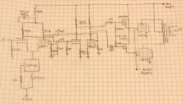
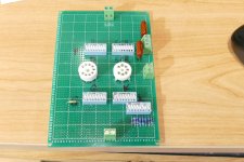
I made a protoboard "module" to see if it would work. This one can take a 7 or 9 pin miniature tube. The heaters are prewired to both sockets, but the cathode, G1, G2, and plate terminals on the board go to DIP switches to select the pin number. I also have a switch for selecting the cathode resistor value, or bypassing it for power supply curve tracing. Obviously use of a system like this requires some thought since random switch flipping can blow stuff up. It is possible to route the plate voltage back into your function generator just by setting the plate and control grids to the same pin number, so plugging the grid cable into a meter before plugging it into the function generator is a good idea.
I am currently laying out PC boards for this generic DIP switch board, and for all of the individual stages of a guitar amp. Pentode gain stage, triode gain stage, tone stack, etc.
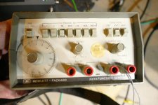
I use a HP3311A function generator that I got cheap at a hamfest and fixed. it can output a triangle, square, or sine wave with an adjustable DC offset. Feed this into the grid terminal of a test board, put a power supply on G2, and a power supply and load resistor or OPT combo on the plate terminal, and find your tube's sweet spot by turning knobs. I have been doing it this way in some variation for as long as I can remember. Load lines have their place, but they really only work on the tubes you see in the tube manual, not the ones in your stash, or circuit.
Remember that OPT's don't have a fixed value like 6600 ohms to 8 ohms. They have a ratio that works over a pretty wide range at 1 KHz. So that 6600 ohm to 8 ohm OPT is also a 3300 ohm to 4 ohm OPT and a 13200 ohm to 16 ohm OPT. You don't need a box full of OPT's, you need a couple and a load bank that goes from about 2 ohms to about 18 ohms in 0.1 ohm steps.
I found a picture that is zoomed in a bit more so that the writing is legible. There was a box full of modules. Each module fit one or more of the popular JEDEC tube base / pinouts. This amp used two that can handle 9A (12AX7 and similar) and 9AJ (6DJ8 6BQ7 etc) tubes and one that handled a pair of 6CK tubes (6AV5). Other modules held the individual components. This worked but having to screw down each wire, or bunch of wires took considerable time.
After 10 years of doing amp design on Tubelab III I got pretty good at just building an amp on perfboard and having it work well enough to start tweaking on so that the Tubelab prototyping system saw less and less use. When my 41 year engineering career at Motorola ended we packed up what we wanted to keep and sold, traded, or gave away what we didn't want, or didn't want to pay to move and store. Tubelab III was useful enough to me that I still have it, but the box full of modules got lost somewhere. We had to get out of Florida on three weeks notice, so lots of stuff got lost, or otherwise diverted from making the trip.
I have been waffling back and forth as to just how to "design" a new guitar amp since I sold or gave away two nice vintage rarities before leaving Florida due to their size and weight. Tube HiFi amps are a known technology, and the goal is generally clean good quality sound. Yes, there are many different opinions about that sound, but guitar amps are a different thing all together. Here we want some "dirt" in our not so clean sound, but not just any dirt, and the flavors are widely varied. I need some way to bend the circuit into multiple different contortions and vary nearly every component in it. guess what I dragged out of storage and cleaned up.
I made a protoboard "module" to see if it would work. This one can take a 7 or 9 pin miniature tube. The heaters are prewired to both sockets, but the cathode, G1, G2, and plate terminals on the board go to DIP switches to select the pin number. I also have a switch for selecting the cathode resistor value, or bypassing it for power supply curve tracing. Obviously use of a system like this requires some thought since random switch flipping can blow stuff up. It is possible to route the plate voltage back into your function generator just by setting the plate and control grids to the same pin number, so plugging the grid cable into a meter before plugging it into the function generator is a good idea.
I am currently laying out PC boards for this generic DIP switch board, and for all of the individual stages of a guitar amp. Pentode gain stage, triode gain stage, tone stack, etc.
I use a HP3311A function generator that I got cheap at a hamfest and fixed. it can output a triangle, square, or sine wave with an adjustable DC offset. Feed this into the grid terminal of a test board, put a power supply on G2, and a power supply and load resistor or OPT combo on the plate terminal, and find your tube's sweet spot by turning knobs. I have been doing it this way in some variation for as long as I can remember. Load lines have their place, but they really only work on the tubes you see in the tube manual, not the ones in your stash, or circuit.
Remember that OPT's don't have a fixed value like 6600 ohms to 8 ohms. They have a ratio that works over a pretty wide range at 1 KHz. So that 6600 ohm to 8 ohm OPT is also a 3300 ohm to 4 ohm OPT and a 13200 ohm to 16 ohm OPT. You don't need a box full of OPT's, you need a couple and a load bank that goes from about 2 ohms to about 18 ohms in 0.1 ohm steps.
Attachments
One might get away with this for the smaller signal tubes. Put it on a card, modified, to bring the control out from the trimpot - and whatever else needed to get any ripple/noise at some mA current load into a usable range. Not bad expense, if it works.

Fahnestock clips, Vector T30 pins, surface mount tube sockets, tube prototyping sockets
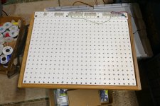
I mount Fahnestock clips under the 4 corner screws of the tube prototyping boards, T30 terminals can also be pushed into the corner holes with an insulating sleeve. (for the bigger sockets I drilled a center hole, so a single woodscrew can hold the whole socket assembly down to the wood base)


I mount Fahnestock clips under the 4 corner screws of the tube prototyping boards, T30 terminals can also be pushed into the corner holes with an insulating sleeve. (for the bigger sockets I drilled a center hole, so a single woodscrew can hold the whole socket assembly down to the wood base)
--Top Secret--
Surface Mount Tube Sockets with Vector T30 spring terminals
Heater wires get directly soldered on, pins 2 and 7. (or 7 and 8 for regulator tubes)

Surface Mount Tube Sockets with Vector T30 spring terminals
Heater wires get directly soldered on, pins 2 and 7. (or 7 and 8 for regulator tubes)
I assume that those top secret T30 spring thingies are the "push down, stick the component wire through the hole" type? If so, can you fit more than one wire in at a time? I can't find any info about them on the internet.
I got some of those spring only thingies like found in the older Radio Shack 50 in one electronics experimenter's kits from Maker Trading Post in Ohio. I may use them, but they can be a challenge with multiple wires and numb fingers.
I got some of those spring only thingies like found in the older Radio Shack 50 in one electronics experimenter's kits from Maker Trading Post in Ohio. I may use them, but they can be a challenge with multiple wires and numb fingers.
Yep, multiple wires fit into a long strip-like hole. Just push down the spring to insert wires, then release. A fairly stiff spring. "Vector T30" will bring up bags of them on Ebay. Unfortunately they're NOT insulated. Kind of a mouse trap for wandering fingers, arrayed out on those sockets. The "surface mount" tube sockets aren't easy to find any more, used to find bags of 10 of them. There don't appear to have ever been any Compactron or Novar versions. The Octal, Nine and Seven pin ones may still show up occasionally, but individual ones are way too overpriced. Probably could make some facsimiles from regular sockets. The tube prototyping sockets on small PC boards with screw terminal strips are a bit pricey too. But much safer! Could be useful to make small PC boards with the T30 terminals around the socket. Not sure the PC foils would stand up to repeated spring depressions or clumsy side-ways pressure. Maybe working with a double-sided PC board with soldering on both sides.
Last edited:
- Home
- Amplifiers
- Tubes / Valves
- This guy is doing this hobby the way I always wanted to do it