Tubelab_com said... The T30-2 wire grabbers from Ebay arrived this morning. They are obviously old and a bit tarnished but will work fine for my breadboard use. These will be used in the construction of several breadboards, each of which will contain one tube socket and the parts for a minimally functional circuit block using the T30 clips to allow for easy solderless parts changing where the dip switch and resistor bank is not feasible. The circuit blocks will be things like a pentode gain stage, phase inverter, dual gain stage with a twin triode tube, FMV triode stack between two triodes. Baxandall tone stack between two triodes.......
Yes! This is where I'm headed when I say "overlay boards", 'topology", 'circuit types" in my previous posts. But for the novice or student, the wiring complexity is in the banana-jacked board with its schematic actually drawn on it. They just wire it with the tube of interest and measure away. Or at an advanced stage chain them up into multi stagezs
Whatever you choose to build you will need a database containing lists of tube numbers with compatible pinouts. These lists can be compiled by sitting down with a pile of tube manuals, several years worth of random notes and a modern state of the art computer built with parts scavenged from the dumpster at the IBM plant in Boca Raton Florida, and a fresh copy of the latest DOS version of Lotus123. Said lists can be continuously updated for a long time, and imported to a newer spreadsheet, MS Excel.
I am including my latest rendition of said spreadsheet, so you don't need to do that. It is believed to be accurate as I fix mistakes when I find them and haven't found any in several years. I do add new tubes as I run across them, and this list is based mostly on tubes that I have, am familiar with, or have looked up for some reason. For this reason, it is mostly centered around US tubes. Anyone is free to use this list for any non commercial reason. All I ask is an email or a forum PM if a mistake is found or another tube needs to be added and you have a data sheet or link to one.
Open it in Excel and you will find tabs for the common tube socket flavors. Pick a base and open a tab to find rows of tubes grouped by their EIA / JEDEC base number. At the top of most pages there is one or more lists of tubes that can be footprint compatible if the socket is WIRED ACCORDING TO THE SOCKET WIRING in the brown stripe. Look at the 7 pin page and you will see one brown stripe. If you wire a socket as shown in the brown stripe, all of the tubes listed in column K, rows 10 through 17 will plug in and offer electrical pin compatibility. Yes, in this case there are tetrodes, pentodes, hexodes, and heptodes, and every one of these tubes has been verified to function in Pete Millett's Engineers Amp, AKA the big red board. Some will work better than others, with my favorite the 6GU5, a hexode working better than the recommended pentode, the 6CB6.
Tubes listed without a brown strip above them are only compatible with others in the same row. Note that pin compatibility does NOT imply direct replacement compatibility. A 6V6GT will have pin compatibility with the 6550, but it won't live long in the 6550 socket. These lists are very useful when making a tube tester or other test board where the external parameters applied to the tube can be adjusted as needed. IE, the "Pentode Gain Stage" test board currently being built is being wired according to the socket wiring stripe in "Group 1 6EJ7 pin compatible" on the 9 pin miniature page. There are 25 tubes listed that should plug into that board and work depending on how the external power and bias supplies are adjusted.
The 12 pin duodecar (Compactron) list refers to three different hacks to Pete's Engineers amp, as it WAS my test board for the 7 pin miniature and 12 pin compactron tube lists.
The spread sheet is included. The date refers to the last time I changed something. I added the 50JY6 tube this month. The change before that occurred in Jan 2022.
Attachments
Wow George that is a fantastic creation.
Thank you it will be very useful and clearly took years to get sorted out. A bit of a life long achievement
Good for you
I am particularly interested in the duodecar listing as I think that is where the interesting tubes are hiding.
Thanks again
Thank you it will be very useful and clearly took years to get sorted out. A bit of a life long achievement
Good for you
I am particularly interested in the duodecar listing as I think that is where the interesting tubes are hiding.
Thanks again
Along the lines of Georges work. I link this thread that KodaBMX built for his Modular Amp 1.
A read through the thread makes it clear how many options there are with many tubes to chose from.
https://www.diyaudio.com/community/threads/modular-amplifier-1.375206/
Myself, I am going to stick with a stackable jumper idea and a board that has a few different tube sockets on it wired to bannana sockets. A few separate variable power supplies. A Se transformer, A PP transformer and a dummy load. Monitor with the O scope and figure out the pairs and optimum operating points. I am not trying to solve too many options just make nice sounding amplifiers. The complexity quickly gets out of hand and really does not lead to much other than more complexity. There are a lot of variables involved each with a great deal of variance. A Rabbithole as George alludes to.
KISS is a good thing to think about
How about fastening some prototyping sockets down to some clear acrylic (plexiglass) and then sliding a white cardboard piece under that with the wire and component connection paths drawn in. Different circuit = different cardboard drawing to slide underneath. The prototyping sockets aren't generally cheap, so this saves considerable cost over repeated parts for separate assemblies. You will have to drill and thread the prototyping socket bolt holes, unless you use a longer bolt and nut.
Good for you Don:
I think this combined with number labeled banana sockets for each pin may answer the pinout pattern question to be able to include far more tubes. It needs far fewer sockets and no pre wiring to match base patterns. It allows for multiple topologies.
I still think the power section and output section will need to be separate but this is a good start.
Hmm, fasten a steel sheet metal plate to the bottom of each prototype socket assembly. Then drill (mill - flat bottom) partial holes in the acrylic beneath them and drop in neodymium magnets (glued in). Now one can change socket types easily. One could even sweep a whole circuit off the board to start another one. Then old circuits could be re-positioned on the board again later. Amaze your friends by taking a circuit off a wall hook and positioning it again on the board to play music.
Better yet. Glue the magnets to the bottom of the prototype sockets and slide a full size steel sheet under the (thin) plexiglass sheet and cardboard/paper circuit wiring pattern layers. Now one can release the whole circuit be sliding the steel sheet out, or just pull sockets off to change pin count etc. No drilling into the plexiglass this way. Everything can be fitted anywhere. Pots, Banana plugs ..., all magnet held too. Maybe some thin sticky rubber adhesive under Pots etc so they don't rotate on the plexiglass easily. Maybe one could do connections with magnets too. Components get leads soldered to steel washers, then stack the washers and drop a rod maget thru the washer holes to fasten. You probably need to alternate or pair up N-S poles among all these held down items so repulsion doesn't build up.
You can get rubberized/ adhesive magnet sheet, similar to what goes on refrigerator door edges. But that probably won't be strong enough to hold things down, unless the plexiglass sheet is left out. Hmm, do we really even need the plexiglass sheet in there now. Just put the paper wiring diagram on top of the bottom steel sheet. Probably can't pull the steel sheet out then to release everything.
You can get rubberized/ adhesive magnet sheet, similar to what goes on refrigerator door edges. But that probably won't be strong enough to hold things down, unless the plexiglass sheet is left out. Hmm, do we really even need the plexiglass sheet in there now. Just put the paper wiring diagram on top of the bottom steel sheet. Probably can't pull the steel sheet out then to release everything.
Last edited:
One problem with this magnet craze though. Magnetic fields can mess up tube electron trajectories. From previous testing, normal tubes get higher Ri with a magnetic field through them. This should be fixable by putting a fitted magnetic shield sheet or cup between the magnet and the tube socket. A glued together sandwich below the socket. A shallow cup like assembly around the magnet is best, so both N and S poles get directed to the steel sheet below. Some magnets may come with this already installed. Solves the repulsion buildup problem too.
Hmm. Velcro instead?
Or double sided adhesive patches?
There is some type of thin flexible plastic sheet that will stick to glass or smooth plastic. I think you wet it 1st to make it stick. All those window decals use it.
Hmm. Velcro instead?
Or double sided adhesive patches?
There is some type of thin flexible plastic sheet that will stick to glass or smooth plastic. I think you wet it 1st to make it stick. All those window decals use it.
Last edited:
Push-in or Snap-in sockets, almost Surface mount.
$0.65 each
If a PVC Pipe Cap fits them, could drill a hole in the pipe cap for a mounting screw and then pop them in after mounting. With T30 terminals around them.


$0.65 each
If a PVC Pipe Cap fits them, could drill a hole in the pipe cap for a mounting screw and then pop them in after mounting. With T30 terminals around them.
Last edited:
"Push-in or Snap-in sockets, almost Surface mount."
These things were made to snap into a hole in the phenolic PCB. There were quite a few AA5 radios made with these things. They used a rather small PCB and 7 pin miniature tubes, which worked for 4 or 5 tube changes. Unfortunately, there were a few TV sets made with them which were total junk. Imagine reaching into your TV set to pull out a tube and finding the socket on the end of the tube with pieces of the copper traces hanging. Use these at your own risk and epoxy them into the PCB or flatten out the pins and screw or glue them to the top of the PCB.
About 15 years ago a forum member here made some prototype sockets like yours. I still have some of his blank boards. Maybe it's time for someone to do it again. Octal relay sockets show up on the usual surplus sites from time to time. Most work fine for vacuum tubes, but the really old crusty looking black plastic kind start to smell funny with a glowing red 6LW6 in the hot seat.
Attachments
Totally agree. The original big hole PC usage for these push-in thingies were disastrous, that's why they're still so cheap. But T30 pins and PVC pipe caps might work out for them. Haven't tried them yet, but got a couple coming soon. Looks like a 3/4" hole PVC pipe cap needed for a 9 pinner.
Last edited:
Greetings from Finland, Europe !
I understand Swedish and Norwegian language is a little bit similar, which means I almost understand what he speaks in Youtube video. Very interesting tube tester. Never seen anything like this before. There was some schematics, maybe it is worth of build a tester like this ? I have only µTracer and it doesn't work without computer and it's not possible to listen how tube sounds if using only µTracer.
I understand Swedish and Norwegian language is a little bit similar, which means I almost understand what he speaks in Youtube video. Very interesting tube tester. Never seen anything like this before. There was some schematics, maybe it is worth of build a tester like this ? I have only µTracer and it doesn't work without computer and it's not possible to listen how tube sounds if using only µTracer.
Early on in the hobby I was sticking magnets on socket boards and parts and breadboards because I did have sheets of steel with walnut veneer over it. As a way to be able to clear my bench then pick up a project again later But I was worried about line/output and power transformers getting near magnets and ruining them. Currently I use vertical spring clips that accept up to 14 gauge wire, these are soldered in rows of 5 just like breadboards for solid state DIP's, etc. I can post a photo of those boards later, for general breadboard fields of connectors I will definitely stick with these.
Tubelab does this hobby the way I would like to.
Push to the limit and then push a bunch more!!
Learning the whole time.
Great fun and you learn alot.
Push to the limit and then push a bunch more!!
Learning the whole time.
Great fun and you learn alot.

My grandfather ran a large factory that made stuff from canvas. Things like his own patented horse collar to circus tents and some outdoor furniture. He gave me a box full of large ornamental brass furniture tacks and a big old soldering iron that was intended for fixing car radiators when I was about 8 or 9 years old. There was a landfill trash dump within a (long) bicycle ride of my house, and people often discarded radios and TV's in their household trash. I never saw a TV that I didn't get something useful from. I grabbed the tubes from any TV I saw and pulled the chassis from some that had useful looking parts, and were small enough to drag home on a bike. My first real electronics creation was a three tube guitar amp made with parts soldered to brass tacks that had been hammered into a pine board.
Even then I had two classes of parts. The good stuff like a rare trash find 6V6 tube, or the "Thoro Test" 6L6GC tube that I paid $1 for at the Eagle Army Navy store in the mid 60's, and the few solid state parts that I could find. There was also my ever expanding collection of "expendables." The 6BQ6GT and 6DQ6 TV sweep tubes were really common, and I had probably a dozen of each. Those were the things used to "push to the limit and then push a bunch more!!" Today I have a box full of 25DN6 tubes that I got for 50 cents each. They are the go to parts for experiments that could end badly, or where I'll just "turn it up till it melts." Since Stan at ESRC passed, my source for "cheap tubes that didn't sell well" is gone so I have to be nice to the good stuff, but I still have about 80 25DN6's and a lot of other "useless TV tubes."
I went to a technical high school in the late 60's and was enrolled in a 3 year long vocational electronics program that taught vacuum tube technology. We had a early version of those white prototyping boards with the zillion holes on 0.1 inch spacing. These were clear about 1/2 inch thick, about 18 X 24 inches in size, and had holes spaced about 1/4 inch apart. Like the current flavor the brass contacts ran in rows that connected about 5 or 6 holes. The holes would accept the leads from 1/2 watt to 2 watt resistors, most capacitors and other small parts. There were "tube carriers" that accommodated a 9 pin or octal tube and plugged into the board much like a DIP chip fits a white board today. These things were marked "DeVry" which was a technical school in the 1960's. I have been looking for one of those for years and have never seen one on EBAY or anywhere else.
The red board in the article here appears to be an older version of the DeVry board. Some other useful ideas here too:
https://www.angelfire.com/electronic/funwithtubes/Breadboarding.html
Last edited:
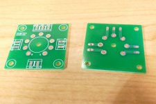
I guess now is as good a time to unveil something I thought might have commercial value in tube breadboarding, something I call my "Tube Tinker" system. I've been obsessed with breadboarding fun since I started this hobby, so that's why this Norwegian mans post was so delightful to me. A while back I found these vertical spring clip that can accept any wide size tightly from 30AWG all the way to 14AWG. Each hole can also accept a bundle of wires of the same diameter, great contact. I've arranged these on a PCB "row" pattern similar to the usual solid state breadboards. Additionally I standardized the mounting hole spacing to accept M3 standoffs where other smaller boards can be stacked for tubes, sub circuits, etc. Additionally I began to make some stand up boards as edge cards that can hold pots, jacks, meters, rheostats, etc. Here are some photos, you get the idea. Also a sample of how one of the many different PCB's shape out. Now that I think of it, I can probably build the pre-wired circuits of Helge's tube tester on edge cards, plugged around the perimeter like he did. Then any circuit, like the opamp for example can be improved later just by making another edge card plug board for it. Note how tube socket overlays can be made and just dropped onto whatever section of the backplane you want it, same for edge card sockets.


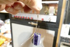
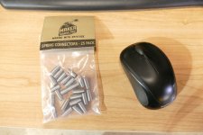
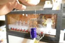
I tried a Wago, and a couple other lift lever solderless wire connectors sold on Amazon. They all failed the 4 wires of three different sizes at the same time test. These little T30 thingies are the clear winner here, though the spring things from Makers Trading Post worked OK as well. It took a bit more fiddling to get all 4 wires into the spring than it did the T30.
Attachments
That post was long so continuing... The more I think of it I should leverage the work I've already done designing (with many JLCPCB iterations) these prototyping boards with these great vertical spring clips. Helge's tube tester nicely arranges the grid, cathode and plate circuits around the perimeter, with metering and power coming in at the top, just like a schematic! If I use edge cards for all the grid, plate, cathode, metering, and powering. Then use a larger version of my proto planes as seen above. I can make a totally modular tube tester, where any part of the circuit can easily be revised by just designing a new edge card for that portion. The modularity comes from edge cards and from the standoffs that allow you to stack smaller "shield" boards (to borrow an Arduino term) in any section of whatever sized backplane field board you chose to use big or small. To date I've made 1x1, 2x2, 1x2, 1x3, 2x3 and 3x3 section backplanes of spring contact fields arranged in rows of 8 and 3 for power bussing. Each "section" is a standard 3 inch x 3 inch board with the corner holes 1/4 inch off each corner as I remember. For a tube testing and experimenting lab I'd maybe PCB design a backplane with a nice large contact field maybe a 4x4 or even 4x5 which would be12x12 inches or 12x15 inches. Edge socket shields can be dropped anywhere on the primeter standoffs to hold the vertical edgecards that provide the grid, cathode, plate, opamp, metering, etc. boards. Exciting stuff for me ideas are flowing, now this is the fun of this hobby! Working with actual parts every day.
I tried a Wago, and a couple other lift lever solderless wire connectors sold on Amazon. They all failed the 4 wires of three different sizes at the same time test. These little T30 thingies are the clear winner here, though the spring things from Makers Trading Post worked OK as well. It took a bit more fiddling to get all 4 wires into the spring than it did the T30.
With these spring clips various diameters in the same hole work as long as they are adjacent sizes, if not these holes are in buses of 8 so just use the adjacent hole for the problematic big wire that is loosening the small wires! Here are these clips, I worked with a China supplier to buy in quantity at a discount, part number KF142V if anyone is interested many different suppliers of this spring clip compete:
- Home
- Amplifiers
- Tubes / Valves
- This guy is doing this hobby the way I always wanted to do it