Pretty impressive. I cant even remember where I got the PT for my single channel "lil tiger"; have to guess McGee or someplace. I bet someone right now has a YT video on how to estimate necessary turns for a PT rewind. You just figured it out by investigation.If this was the case, I ripped off every outer winding and wound a new secondary. Simple math and a careful turns count of the 5.0 and 6.3 volt windings provided the needed info for the correct number of secondary turns.
I recall those with the 5U4 on top; never seen the dual though.
In my early teens, my next door neighbor bought a Heathkit AR-13 stereo HiFi receiver kit. On first power up some "stinky smoke" appeared, and the fuse blew. Of course, someone who made their living promoting quack medicine did the expected. The only similar looking fuse he had was for a car, so he tried it which released a lot more stinky smoke. At this point he summons me, the kid that plays with electricity. I didn't need to open the amp up to know where to look because I had already become well aware of the unique smell of vented electrolytic goo. Sure enough one of the power supply caps had been installed backwards, so I told him to go to the Heathkit store to fetch a new one. It took a couple days to get the part during which time I copied the power amplifier schematic by hand (copy machines were rare in 1965) and explored the possibility of cloning it. The only stumbling block was the driver transformer. The schematic told me that there were three windings. My trusty Eico VTVM told me that the primary had more resistance than the two equal resistance secondaries. The Heathkit store wanted too much money for it, so the clone idea stalled.
Before I ever got around to cloning the AR-13's power amp the Lil Tiger amp design appeared in a magazine article. The PCB design was simple enough that it could be made with some Ferric Chloride and masking tape, done deal. By 11th grade I had three of them, a pair for my audio system and a third for my guitar amp that still rocked an all germanium preamp built on perf board. Initially these were all powered with multiple interconnected 6.3 and 12.6 volt transformers from Radio Shack.
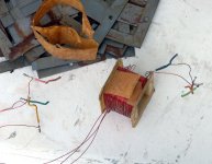
Sometime around 1970 I wandered into a surplus shop near the Miami Airport called the "Ham Shack" and discovered a big bin full of identical NPN Silicon TO-3 power transistors with house numbers on them. The bin said "2N3055." They were $1 for one, 50 cents if you bought 10 and 25 cents if you bought 100, so I got 100, and still have a few left. I don't know what they really were, but they lived on a 100 volt supply and instantly shorted on 155 volts. Now, what do I do with them.???? It took about 15 minutes to dig up the Heathkit schematic, about an hour to rip all the wire off the bobbin from a Radio Shack filament transformer and hastily scramble wind three trifilar windings on to it until it was about 2/3ds full then continue until the bobbin was full with the third wire. Experiments with a pair of mystery transistors, my DIY transformer, and a LiL Tiger to drive it revealed lots of audio power to be had. If one pair of transistors was loud, what about two pair, or more? What could I use to power this beast?
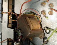
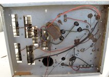
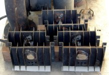
A random pit stop in a metal scrapyard that would soon become famous by receiving all remains of Eastern Airlines flight 401 after it crashed into the Everglades about 20 miles to the west yielded a new 75 volt 4.5 amp transformer for $10! Time to build the "big one." With nothing but drill and a nibbling tool (remember those) I hacked up a large Bud chassis and made a booster amp with 6 of the mystery transistors and my DIY driver transformer. Feed int this beast with my DIY Lil Tiger based guitar amp made me the loudest (far from the best) guitar player in the high school of about 3000 students. This amp lived on through high school without failure and was eventually forgotten about when I left home two years later. A dozen years or so later my brother brings me a couple boxes of stuff he had hidden when my father threw out all of the stuff that remained when I left home. The old booster amp was in the box. I stashed it in an outdoor shed where it remained until Hurricane Wilma trashed the shed and I rediscovered the long forgotten amp.
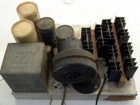
A quick look revealed the crude techniques I used in the 1960's including the power cord being connected directly to the power transformer with no switch or fuse. That left only one thing to do, get a long extension cord stand back and plug it in. I gave it a small chance of working and a large chance of something else happening. As soon as the power cord hit the wall outlet the outcome was obvious. The blower fan spun up, then started to slow down. The line cord got pretty warm and the breaker tripped. About a minute later the "stinky smoke" appeared. One of the power supply caps had vented. Game over. I kept the heat sinks with transistors, ripped the driver transformer apart to see how it fared, and trashed the rest.
This thing had been stored outdoors in one of two sheds for nearly 40 years. The transformer had grown some rust, and the masking tape I used had dried out a bit, but I think that it would have worked. I know that some of my TV power transformers with new secondaries insulated with masking tape lived until I lost track of them in the1990's, maybe longer.
Before I ever got around to cloning the AR-13's power amp the Lil Tiger amp design appeared in a magazine article. The PCB design was simple enough that it could be made with some Ferric Chloride and masking tape, done deal. By 11th grade I had three of them, a pair for my audio system and a third for my guitar amp that still rocked an all germanium preamp built on perf board. Initially these were all powered with multiple interconnected 6.3 and 12.6 volt transformers from Radio Shack.
Sometime around 1970 I wandered into a surplus shop near the Miami Airport called the "Ham Shack" and discovered a big bin full of identical NPN Silicon TO-3 power transistors with house numbers on them. The bin said "2N3055." They were $1 for one, 50 cents if you bought 10 and 25 cents if you bought 100, so I got 100, and still have a few left. I don't know what they really were, but they lived on a 100 volt supply and instantly shorted on 155 volts. Now, what do I do with them.???? It took about 15 minutes to dig up the Heathkit schematic, about an hour to rip all the wire off the bobbin from a Radio Shack filament transformer and hastily scramble wind three trifilar windings on to it until it was about 2/3ds full then continue until the bobbin was full with the third wire. Experiments with a pair of mystery transistors, my DIY transformer, and a LiL Tiger to drive it revealed lots of audio power to be had. If one pair of transistors was loud, what about two pair, or more? What could I use to power this beast?
A random pit stop in a metal scrapyard that would soon become famous by receiving all remains of Eastern Airlines flight 401 after it crashed into the Everglades about 20 miles to the west yielded a new 75 volt 4.5 amp transformer for $10! Time to build the "big one." With nothing but drill and a nibbling tool (remember those) I hacked up a large Bud chassis and made a booster amp with 6 of the mystery transistors and my DIY driver transformer. Feed int this beast with my DIY Lil Tiger based guitar amp made me the loudest (far from the best) guitar player in the high school of about 3000 students. This amp lived on through high school without failure and was eventually forgotten about when I left home two years later. A dozen years or so later my brother brings me a couple boxes of stuff he had hidden when my father threw out all of the stuff that remained when I left home. The old booster amp was in the box. I stashed it in an outdoor shed where it remained until Hurricane Wilma trashed the shed and I rediscovered the long forgotten amp.
A quick look revealed the crude techniques I used in the 1960's including the power cord being connected directly to the power transformer with no switch or fuse. That left only one thing to do, get a long extension cord stand back and plug it in. I gave it a small chance of working and a large chance of something else happening. As soon as the power cord hit the wall outlet the outcome was obvious. The blower fan spun up, then started to slow down. The line cord got pretty warm and the breaker tripped. About a minute later the "stinky smoke" appeared. One of the power supply caps had vented. Game over. I kept the heat sinks with transistors, ripped the driver transformer apart to see how it fared, and trashed the rest.
This thing had been stored outdoors in one of two sheds for nearly 40 years. The transformer had grown some rust, and the masking tape I used had dried out a bit, but I think that it would have worked. I know that some of my TV power transformers with new secondaries insulated with masking tape lived until I lost track of them in the1990's, maybe longer.
Attachments

So, if you had brought it up using a Variac, say, ~20V increments over an hour, would that have given the offending cap a chance at survival and further service?
With something old and hasnt been powered up in a while, I try to do that, or similar practice as a matter of course. Just wondering if it matters?
With something old and hasnt been powered up in a while, I try to do that, or similar practice as a matter of course. Just wondering if it matters?
I have used the 576 for tubes -- was able to purchase surplus plug-in adapter not yet changed over to tubes.
Happy to help out if you have any issues converting it to tube tracing. One of those 10X Grid Step Amplifiers, like on Ebay (or a similar HomeBrew amplifier, to -200V) is the easiest.
The one issue then is some scheme to turn on screen V to a tube, -only- while curve tracing the tube (ie, only when plate V is present). I used a contact set on the big "Left or Right" toggle switch up front. The contact was used for a remote sense line for high current SS. I put some Banana jacks in up front (yellow jacks) so it can still be used ether way. Each tube gets it's own screen supply via those contacts, made available by 2 double sets of Banana jacks up front (red & white jacks).
Oh, and I put in a small toggle switch to over-ride the safety cover switch.
I also recommend modding the rectifier wiring (internal to the 576 on the left cover side) to change the max collector/plate V scale from 1500V down to a safer 750V scale. Improved Safety and because that Left-Right toggle switch in the box is not really rated to handle 1500V across it's contacts. It arced over in the one here, and I had to change some switch layer insulators.
I have another box to convert yet for the 2nd 576. Although the boxes -can- just be swapped to go from SS to Tube.
Last edited:
The old booster amp had lived all of its useful years long ago. Even if it still worked, it would have met the scrap heap. After it was gone, I had second thoughts about tossing the transformer, but it would have met the fate of between 500 and 1000 pounds of transformers and a similar amount of weight bench and workout weights when it was time to move everything I owned or wanted to keep 1200 miles. Most people live up north and retire in Florida. I lived in south Florida for 62 years and retired to snow country.So, if you had brought it up using a Variac, say, ~20V increments over an hour, would that have given the offending cap a chance at survival and further service?
With something old and hasnt been powered up in a while, I try to do that, or similar practice as a matter of course. Just wondering if it matters?
I ordered some of the KF142V green and orange connectors in 2, 3 and 5 pin flavors from LCSC in China on Tuesday. I also ordered a few 4 pin connectors from Amazon at the same time with a two to three week delivery date. It now appears that both sets may be here in the next few days. I have been working on small single PCB layouts for each of the common stages in a typical guitar amp, with hooks for lots of experiments and some different flavor tubes. It may help speed up that process to just stick a 12AX7 socket on perf board and start wiring up the non-connectorized stuff now.
For George...
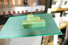
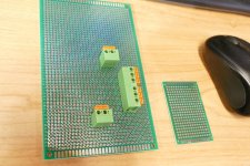
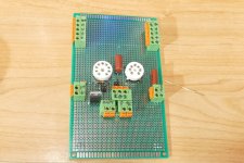
If you have some spring terminals arriving here is a mechanical drawing that works well for creating a "field" of tie points on a plane so you don't have to go through the trial and error I did. This example uses 3 pin and 8 pin terminals, but any number of pins can be adapted. As long as the "long side" to "long side" spacing is 7.62mm and the "short edge" to "short edge" spacing is 8.255 mm (hole to hole) then the terminal blocks will form an even field of holes (similar to DIP breadboard holes). And the push levers have room to swing with this arrangement. I had to go through more JLCPCB iterations than I care to think about to get this spacing right, so saving others the cost if they use these terminals. Also by trial and error I found that 1.2 mm pin holes work best with the OD of the pads being 2.4 mm. The buss traces run horizontally across, this example has 8 busses of 5 tie points (40 holes) and 2 groups of 3 busses with 3 tie points (total 18 holes). For this spacing example below is the PCB layout, the mechanicals, spacings, etc. for the same and a photo of another board bottom once its all soldered up. I ran 3mm traces on both sides to increase current handling. I also noticed I'm using M4 nylon standoffs as the way to stack boards, earlier I thought they were M3. Again the long side to long side and short side to short side hole distances are all that matters regardless of how many pins your terminals have.
Sample PCB using 6 three pin terminals and 5 eight pin terminals:

Dimensions for same PCB:

Soldered up bottom example, this board has the above field pattern duplicated 4 times (2x2):

If you have some spring terminals arriving here is a mechanical drawing that works well for creating a "field" of tie points on a plane so you don't have to go through the trial and error I did. This example uses 3 pin and 8 pin terminals, but any number of pins can be adapted. As long as the "long side" to "long side" spacing is 7.62mm and the "short edge" to "short edge" spacing is 8.255 mm (hole to hole) then the terminal blocks will form an even field of holes (similar to DIP breadboard holes). And the push levers have room to swing with this arrangement. I had to go through more JLCPCB iterations than I care to think about to get this spacing right, so saving others the cost if they use these terminals. Also by trial and error I found that 1.2 mm pin holes work best with the OD of the pads being 2.4 mm. The buss traces run horizontally across, this example has 8 busses of 5 tie points (40 holes) and 2 groups of 3 busses with 3 tie points (total 18 holes). For this spacing example below is the PCB layout, the mechanicals, spacings, etc. for the same and a photo of another board bottom once its all soldered up. I ran 3mm traces on both sides to increase current handling. I also noticed I'm using M4 nylon standoffs as the way to stack boards, earlier I thought they were M3. Again the long side to long side and short side to short side hole distances are all that matters regardless of how many pins your terminals have.
Sample PCB using 6 three pin terminals and 5 eight pin terminals:
Dimensions for same PCB:
Soldered up bottom example, this board has the above field pattern duplicated 4 times (2x2):
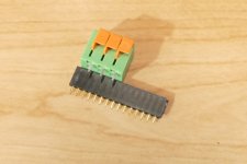
Thanks for the info. The 2 pin, 3 pin, and 5 pin, KF142V terminals arrived today. The 4 pin versions were last seen in New York after a pit stop in Miami. I figured out that these things plug right into the double sided proto boards I got from Amazon years ago. They can also be stacked end to end in the proto board to make odd sizes. Since these test boards will be one-off's I'll just build them on the proto boards.
They have the same pin spacing as a DIP IC chip with every other pin missing. They plug into some IC chip sockets too. They will NOT fit into a machined pin socket due to the width of the pins. They WILL fit into the 0.100 inch snappable headers that come from Amazon, which will fit into small holes. They hang onto the wire pretty good too.
The holes in many of the single sided boards from Amazon are too small for the pins on these connectors. The exact double sided boards I have are no longer listed on Amazon, but there are lots that look the same. I ordered a five for $9.79 pack today, delivery on Friday. I'll test fit the terminals in them when they arrive.
Are you going to the Dayton Hamfest this year? I will be in the same spot as last year.
Attachments
Are you going to the Dayton Hamfest this year? I will be in the same spot as last year.
The dates look good for a drive to Ohio, if my wife has no conflict then we'll be there. Last year we stopped at the Air Force museum at Write-Patterson air force base which was very much with the visit. Always a fun way to start the summer. The double pin spacing makes them better for higher voltages too if you make PCB's.
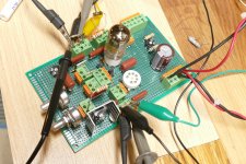
The first of several individual amp stage test bords is about half done. My ADHD powered brain has convinced me to back up and change stuff mid stream several times already. I started with the most complicated design first thinking that it would all be downhill from there, but it might not have been the best plan. Today, I will stop and trace out a schematic of what's actually on this board before going any further.
There will be several boards like this one from "simple triode gain stage" to "offspring of UNSET meets SATURATOR" which is the one being built. The concept has two tube sockets, one 7 pin and one 9 pin. Only one tube will be installed at a time. The board can be configured as a simple common cathode pentode gain stage, a pure UNSET gain stage, a pure saturator gain stage, or UNSET and saturator at the same time. Configuration depends on what is placed in the green and orange connectors. There are a few pin header jumpers to swap tube pinouts to accommodate about 100 different type number small signal pentodes. Lots of data regarding gain and distortion VS operating conditions will be taken on each tube type.
Once some basic data has been collected two or more of these test boards will be connected together to make an amplifier or three.
Attachments

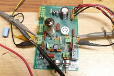
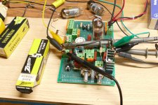
The "offspring of UNSET meets SATURATOR" test board is operational, as configured in basic common cathode pentode gain stage mode. The no so mainstream modes have yet to be tried. I stuffed my "best guess" values for the pluggable parts, based mostly on what was lying around on the bench, stuffed in a 6KT6 tube and hit the power switch. There is 100 volts p-p of output for 1.2 volts P-P of input and the signals look clean, so now the real science experiments begin.
As the guy on TV said, "It's safe to assume that something will go boom." Small parts, low current, wimpy power supply...........no big booms though.
As the guy on TV said, "It's safe to assume that something will go boom." Small parts, low current, wimpy power supply...........no big booms though.
Attachments
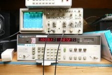
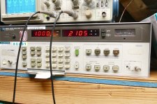
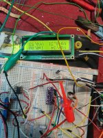
Saturator mode engaged. With "first guess" parts values the gain at max setting is 546 V/V.
With 100 mV RMS at the input the output is 54.6 V RMS @ 0.566% THD.
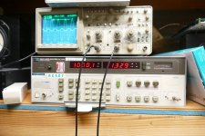
With 200 mV RMS at the input the output is 107.2 V RMS @ 1.329% THD.
With 250 mV RMS at the input the output is 125.3 V RMS @ 7.06% THD.
With 300 mV RMS at the input the output is 134.5 V RMS @ 12.76% THD.
With 400 mV RMS at the input the output is 146.0 RMS @ 20.29% THD.
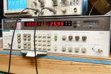
With 500 mV RMS at the input the output is 25.14 V RMS @ 25.10% THD.
The gain at minimum setting is 81.6
The saturator design has been used successfully in a low power guitar amp where it was constrained by a B+ voltage of 165 volts. Here I have the power supply maxed at 450 volts. The saturator is a conventional pentode gain stage with its plate load resistor bootstrapped with a buffered version of the pate voltage its other end making it look like a very high impedance. This is similar to the bootstrapped driver that McIntosh used in their unity coupled amplifiers. 300+ volts peak to peak at 1.33% THD should drive the grid right out of most any tube that we will see.
With 100 mV RMS at the input the output is 54.6 V RMS @ 0.566% THD.
With 200 mV RMS at the input the output is 107.2 V RMS @ 1.329% THD.
With 250 mV RMS at the input the output is 125.3 V RMS @ 7.06% THD.
With 300 mV RMS at the input the output is 134.5 V RMS @ 12.76% THD.
With 400 mV RMS at the input the output is 146.0 RMS @ 20.29% THD.
With 500 mV RMS at the input the output is 25.14 V RMS @ 25.10% THD.
The gain at minimum setting is 81.6
The saturator design has been used successfully in a low power guitar amp where it was constrained by a B+ voltage of 165 volts. Here I have the power supply maxed at 450 volts. The saturator is a conventional pentode gain stage with its plate load resistor bootstrapped with a buffered version of the pate voltage its other end making it look like a very high impedance. This is similar to the bootstrapped driver that McIntosh used in their unity coupled amplifiers. 300+ volts peak to peak at 1.33% THD should drive the grid right out of most any tube that we will see.
Attachments
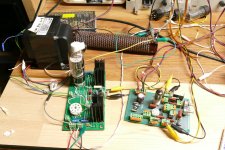
I'm starting to do some design for a stand-alone tube tester and experimenter platform like Helge's. First the power supply. I have been disappointed in my current 1950's 60's HV bench power supplies. They have all been wonky, bouncing needles on the meters, dirty pots, one of them blew a transformer, easily overloaded, etc. problems for both the Heathkit and the Eico supplies. I may sell them "for parts" on ebay. So I have three small "variacs" unhoused smaller than a 6oz coffee cup, typically they are used as dimmer banks in stage theaters (prior to LED's) to smoothly dim incandescent stage lights. So I designed this Filament, B+ and Bias C supply around those little variacs below. It will be housed in a non-metallic enclosure. By using "totem" poled unregulated and regulated supplies I can obtain course and fine adjustment without the hassle of complex Maida or other HV regulation. Also voltages over 1000 VDC and @350 mA are possible (not that I will go there) just by swapping a transformer. The "fine adjust" occurs in the lower supply 0 to 30 volts and the "course adjust" is in the totem poled upper supply 30 to 650 volts. So you just get close with the variac then use the fine supply to be exact. I have some nice used Beckman 25 turn instrument pots I picked up at Hamvention that can find a home finally. Below is the design and a photo of these small theater/banquet hall type lighting dimmer variacs, they are rated 2.5 amp, more than enough even for the filament supply adjust.

This is only a 6oz coffee cup, the variac is under 3 inches in diameter and about 2 inches deep.

This is only a 6oz coffee cup, the variac is under 3 inches in diameter and about 2 inches deep.
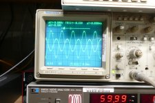
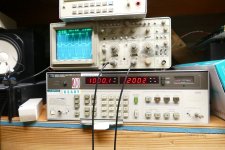
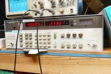
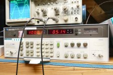
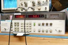
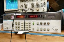
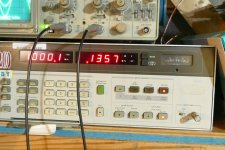
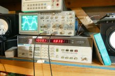
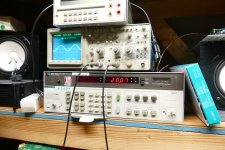
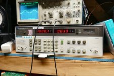
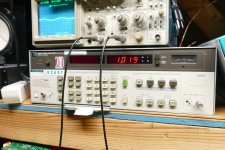
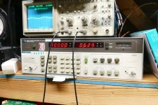
So you try to make a guitar amp where some distortion can be a good thing...........and you accidentally come up with a driver stage that puts out 50 volts RMS (over 140 V P-P) at 0.514% THD using vacuum tubes that I got for 35 cents each! Sloppy wiring with no shielding and floating AC heater supply raises the THD at lower outputs making the true performance. Engaging the 400 Hz High Pass filter on the Audio Analyzer ignores the hum and its lower harmonics. Here 26 volts RMS comes in at 0.113% THD.
Next up, try a $1 tube. Maybe it's twice as good?
Next up, try a $1 tube. Maybe it's twice as good?
Attachments
-
 OutputTHD_NoFilter.JPG457.1 KB · Views: 77
 -
 OutputTHD_With Filter.JPG448.5 KB · Views: 68
 -
 OutputVoltgaeWith 0.68V of Drive.JPG458 KB · Views: 80
 -
 OutputTHD.JPG354.6 KB · Views: 66
 -
 OutputVoltage_RMS.JPG415 KB · Views: 81
 -
 InputTHD.JPG337.4 KB · Views: 68
 -
 InputVoltage_RMS.JPG481 KB · Views: 85
 -
 P4020456.JPG480.5 KB · Views: 74
Many years ago I went down the Variac - Industrial transformer - bridge rectifier - Big A$$ Cap route. Antek did not exist then. I needed something with two equal but independent voltage sources to play with circlotrons since I had several hundred 6AS7G tubes. "Industrial Transformer" or "Industrial Control Transformers" come in several flavors, but the most common ones have a pair of 240 volt windings and a pair of 24 volt windings, a pair of 240 volt windings and a pair of 120 volt windings, or a pair of 120 volt windings and a pair of 24 volt windings. They come in sizes from 50 VA to HUGE and they work well "backwards" fed by a Variac to turn 120 volts into a pair of 0 to 240 volt windings.
My DIY power supply from the early 2000's used a similar transformer with a pair of bridge rectifiers and some big caps to make a pair of 0 to 380 volt floating power supplies. I used a smaller transformer that had a pair of 24 volt secondaries for an adjustable heater supply. The only drawback was the weight. That bad boy was HEAVY, but I could lift it then. I can no longer get my big HP power supply on the second shelf of my workbench since it has a similar sized transformer. Today I would use Antek toroids to do the same thing, though surplus industrial transformers often show up on Ebay, the shipping is often more expensive than the transformer. I might still have a box full of Variacs somewhere and maybe some low voltage toroids. PM me if you are interested. It's time to start making the "take stuff to the hamfest" pile.
Something else that I learned the hard way long ago is that fuses made for AC use will EXPLODE when they blow on DC if the voltage and current capability is high enough. DC fuses rated for 600 volts are expensive. There is no easy solution that I know of.
Any time you connect two power supplies in series, put a big diode across the output of each supply. It should be rated for more current than the supply will make and as much voltage as the biggest supply puts out. This prevents the weaker of the supplies from being eaten by the bigger one if the output of the series connected supplies is accidentally shorted. The diode may fail in case of such a short but diodes usually fail to a shorted condition protecting the supply provided its line fuse blows.
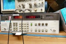
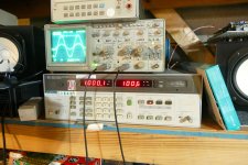
On a slightly different note, I ran a bunch of different tubes from my pentode gain stage test board with some more surprises. The $1 (when I got them) 6JD6 did work better than the 6KT6. Just to see what would happen I put a WWII surplus 6AK5 in the hot seat and it put out 50 volts RMS at 0.372% THD. I used to have thousands of them. The clear winner of tonight's testing was the $3 (current price) 6CB6. I tried 3 new ones and all beat the 6AK5 as did two old and ugly ones. The best of the bunch made 50 volts RMS at 0.1357% and 100 volts RMS at 0.838% THD.
My board has developed a case of random disappearing output and does not work with a couple tubes I need to test, so I am tearing the setup apart to investigate.
My DIY power supply from the early 2000's used a similar transformer with a pair of bridge rectifiers and some big caps to make a pair of 0 to 380 volt floating power supplies. I used a smaller transformer that had a pair of 24 volt secondaries for an adjustable heater supply. The only drawback was the weight. That bad boy was HEAVY, but I could lift it then. I can no longer get my big HP power supply on the second shelf of my workbench since it has a similar sized transformer. Today I would use Antek toroids to do the same thing, though surplus industrial transformers often show up on Ebay, the shipping is often more expensive than the transformer. I might still have a box full of Variacs somewhere and maybe some low voltage toroids. PM me if you are interested. It's time to start making the "take stuff to the hamfest" pile.
Something else that I learned the hard way long ago is that fuses made for AC use will EXPLODE when they blow on DC if the voltage and current capability is high enough. DC fuses rated for 600 volts are expensive. There is no easy solution that I know of.
Any time you connect two power supplies in series, put a big diode across the output of each supply. It should be rated for more current than the supply will make and as much voltage as the biggest supply puts out. This prevents the weaker of the supplies from being eaten by the bigger one if the output of the series connected supplies is accidentally shorted. The diode may fail in case of such a short but diodes usually fail to a shorted condition protecting the supply provided its line fuse blows.
On a slightly different note, I ran a bunch of different tubes from my pentode gain stage test board with some more surprises. The $1 (when I got them) 6JD6 did work better than the 6KT6. Just to see what would happen I put a WWII surplus 6AK5 in the hot seat and it put out 50 volts RMS at 0.372% THD. I used to have thousands of them. The clear winner of tonight's testing was the $3 (current price) 6CB6. I tried 3 new ones and all beat the 6AK5 as did two old and ugly ones. The best of the bunch made 50 volts RMS at 0.1357% and 100 volts RMS at 0.838% THD.
My board has developed a case of random disappearing output and does not work with a couple tubes I need to test, so I am tearing the setup apart to investigate.
Attachments

Thanks, I forgot all about fuse voltage ratings, the most important fuse is on the variac poles though and that is AC within voltage limits. I will omit the B and C DC termination fuses in light of this hazard. I think I understand about the diodes on series supplies from way back, I remember reading that when hooking SMPS supplies in series. I'll add those or make sure they are incorporated on the two flavors of PCB boards shown, HV unregulated and LV regulated. This would make those boards inherently safer for series stringing. Your experiment is interesting, it will be cool to see its application and theory in a circuit.
Hello to all members of this forum, my name is Fernando and I'm from Portugal. This is my first post on this forum. I wanted to ask for help in building a simple tube tester based on Arduino like this one: http://agalavotti.altervista.org/TubeTester1/TubeTester1.html I did a test assembly and encountered the following problems. I only get the correct readings for Vg, Va, and Vf, but they are much below the input value. As for Ia, I wanted to ask for help on where to connect the A2 port of the ADS1115 to the analog part of the circuit. My goal is to test normal tubes ecc81,82,85,88, El84, el34, etc. I appreciate anyone who can help. Thank you, Fernando
Attachments
I added protection diodes and other things to the bench power supply, thanks George. Trying to depict modularity. Hoping to design just two PCB boards one for regulated (LM1084, etc) and one for unregulated (with gyrator or cap multiplier, etc.) to re-use in making any of the PSU modules shown.

Hello to all members of this forum, my name is Fernando and I'm from Portugal. This is my first post on this forum.
Welcome to the forum. I think your question would be best served if you started a new thread topic as a "New Post". The type of tube tester you are making is entirely different than what is being discussed here, which is more of an open brainstorming session for a circuit experimenting platform. Also Arduino related questions may have few people able to help you.
Musicians often talk about their "happy accidents." This is the term that is used to describe an event that occurs occasionally during the song writing process where some writers block is involved, and a break is taken. Sometimes while just playing with an instrument making "noise" or random bits of "musical nonsense" the person realizes that something that fits their intended song just occurred, subconsciously. Often this realization occurs minutes, hours, or days after it was played. This is why the DAW is always recording even when "goofing off." A Digital Audio Workstation is a piece of software that runs on a PC or Mac that can emulate a tape recorder (Audacity) or a full multitrack recording studio.
Well sometimes the Big Dumm Blonde One has happy accidents, and I haven't even picked up the guitar yet. Back in the 1970's I set out to build a frequency synthesizer for a ham radio transceiver, as one chip synthesizers did not yet exist. That project failed miserably but it's remains morphed into an awesome digital darkroom timer and several copies were made for my friends since "everybody" had a darkroom back in the film days.
I built a test board with the intention of inventing some unique tech for a guitar amp. The idea was to combine a circuit known to have extreme voltage gain and a cool sounding distortion characteristic, the "Saturator" which was created for a low budget guitar amp, with the UNSET which is a method for getting triode curves with TV sweep tubes where the low screen grid voltage rating prevents the typical "connect the screen grid to the plate" triode connection. I expected this combination to have lots of gain and cool sounding distortion, but I got neither. What I did get was a circuit with the ability to put out lots of AC drive voltage with really low distortion. Some cheap tubes consistently make 50 volts RMS of output with THD below 0.1% with voltage gains of over 50. 13 different 7 pin tube types all can make 50 volts at less than 0.4% THD. I haven't gotten to the 9 pin tubes yet, though a few are known to work.
The original UNSET board worked great, but its overall voltage gain was a bit too low. It was not possible to drive a 15 watt SE amp to clipping from some CD players or phones. So just to see what would happen, I connected the test board up to an UNSET output stage. So, I set out to design a new gain stage for a guitar amp, and that still may happen, but what's on my bench now looks a lot like an UNSET II. How's 20 watts at 2% THD (edge of clipping), 10 watts at 0.84% and 1 watt at 0.63%.
Now that this stuff has taken over my bench, I will do some serious UNSET tweaking. Even more overall gain is possible. If one output tube is good, two must be better, right? How about a bigger tube? Wait, something's wrong here. I haven't even plugged my guitar into this thing yet.........
Attachments


Well, dont accidentally overwrite that file! Maybe there's a darling there for music listening, versus creating. Of course, it depends on the type of distortion it is. What kills me is the phase of the distortion, relative to the fundamental, matters too in how is sounds. How's that controlled? A little bend in a ideally straight transfer function being convex or concave?So, I set out to design a new gain stage for a guitar amp, and that still may happen, but what's on my bench now looks a lot like an UNSET II. How's 20 watts at 2% THD (edge of clipping), 10 watts at 0.84% and 1 watt at 0.63%.
Keeping within the context of a tube tester, I'm all for a tube tester that you can listen to. They somehow left that feature out of the EICO 666. No speaker, like in their signal tracer... There's a dial that's labeled "grid"; would it have been so hard to put a BNC there to introduce a little wiggle about that control setting with whatever signal was connected? Another BNC to take an AC coupled sample of the result coming off the plate?
We used to test DC-DC converters for transient load response, with a large part of the load stepping well above the audio range. I actually occurred to me to do a frequency shift back down into audible range and let the technician "listen" to the converter's response. I bet with practice they'd quickly pick out a control loop that needed work. Instead, we did frequency duty cycle sweeps that took an hour and made a nice 3D plot you could look at.
- Home
- Amplifiers
- Tubes / Valves
- This guy is doing this hobby the way I always wanted to do it