I have been working and working and working................. And if Im not working I have my two kids to take care of.
I know how to stabilise the bias and I will upgrade the circuit as soon as possible.
Thank for showing interest in my little project!🙂
I know how to stabilise the bias and I will upgrade the circuit as soon as possible.
Thank for showing interest in my little project!🙂
Circlomanen, I've missed your posts as well.
What really appeals to me is because of the symmetry one channel could consists of two very small optimised pcbs, mounted back to back or even at right angles. Also, it means only half the design effort 😀
Hope to hear more when you have the time. The kids are more important.
What really appeals to me is because of the symmetry one channel could consists of two very small optimised pcbs, mounted back to back or even at right angles. Also, it means only half the design effort 😀
Hope to hear more when you have the time. The kids are more important.
I have a minimalistic 200 watt squarewave generator....
I have modified my bias adjustment and added a couple of source resistors and when fireing up the amp the speaker just let out a terrible fast pecking roar and the speaker started to smell burnt paper.
FU:K!!!!
I have modified my bias adjustment and added a couple of source resistors and when fireing up the amp the speaker just let out a terrible fast pecking roar and the speaker started to smell burnt paper.
FU:K!!!!
bummer!
THAT's truly terrible!
I've always feared that scenario and made up a resistive dummy load years ago that I still use religiously. Never did the light bulb trick with an audio amp, but that was my test load of choice when I was a young HAM Radio operator. Hadn't thought of it as a component of the output circuit until Nelson showed us the light [sorry, couldn't resist... oh no, double pun!]
In the words of someone wiser than I...
"I hate it when that happens."
My condolences,
LarryO
Thanks Igo51!
The speaker survived but sounds a bit harsh nowdays. It is a very cheap litle thing built mainly as an experment. But I like it and a will probably buy a new set of woofers once the amp is up and running properly. Now I have installed a 47 ohms power resistor in series with the speaker so it should survive a couple of seconds longer when playing a 200 watt 100 hz squarewave.
I cant figure out why it misbehaves??? Any suggestions or ideas???
Circlomanen said:<snip>I cant figure out why it misbehaves??? Any suggestions or ideas???
I don't recall if your PS is fully linear or regulated, but if the former then you might consider using a variac to control the mains voltage, ergo the PS output voltage, for inspection work.
Also, an old HAM Radio trick is to place a load resistor in a jar filled with mineral oil to increase the effective heat dissipation capacity, ergo power handling. I no longer recollect the rules of thumb but i'm guessing that a 5x to 10x power factor (not sustained for long times) could be achieved. So a junk box 10 - 25 Watt ceramic resistor might be able to handle your load for brief testing runs... try not to boil the oil 😱
Also, consider returning to the previous circuit topology for some baseline tests.
Sorry, not much specific help with the spinning currents but maybe you can spare those favorite speakers from the BBQ.
Regards,
LarryO
mrothacher said:Search for "Zirclotron"
Here's a juiced up version driven by a BOSOZ.🙂
Hhmmm, might the gate stoppers for the 2nd and 3rd output FET pairs be connected to the wrong side of the gate stopper for the 1st pair? I.E. R27-28/R30-29 should connect to the signal source side of R31/R32 instead of the gate side - as shown.

Just curious,
LarryO
mrothacher: You could not get both current and voltage gain from your original zirclotron because of no groundreference. As Nelson Pass said you could use a input transformer with split secondarys to use two groud connections. One for each half of the circuit.
I have been fooling around with the same kinds of circuits the last 4 years.
The Zenitron is a way to isolate the source pins from the drains in order to get voltagegain.
I have been fooling around with the same kinds of circuits the last 4 years.
The Zenitron is a way to isolate the source pins from the drains in order to get voltagegain.
Circlomanen said,
mrothacher: You could not get both current and voltage gain from your original zirclotron because of no groundreference
I disagree.
The original zirclotron seems to have a voltage gain of
approximately one. It also has current gain.
Tom
Circlomanen, Tom2:
I'd originally contemplated a full article on the Zirclotron, but I always figured that a power buffer wouldn't be of much interest.
You guys are clearly much more knowledgeable on this subject.
I'd love to see a suitably simple zen circlotron.
Perhaps Nelson would provide some guidance for a colaboration. I have a decent prototype shop and good test equipment. I'd be willing to provide the elbow grease.
I've also tried to work out a full-bridge Zen with all N mosfets, but my one year of electonics school fizzles out quickly.
I'm a heck of computer / web programmer, tho. I'm also a decent technical writer/editor, and all around lacky. What do you say Nelson? Anything I could do for you in exchange for a few tidbits?
Sincerely,
Mike /Autograph hound - finally got NP's at CES.
Circlomanen:
It occurs to me that a power transformer could be used in your original circuit, ala ZV7... Could it not?
Thanks
Mike
It occurs to me that a power transformer could be used in your original circuit, ala ZV7... Could it not?
Thanks
Mike
Yes, probably.It occurs to me that a power transformer could be used in your original circuit, ala ZV7... Could it not?
For me it was cheaper winding my own chokes, so I have never given it any serious thought.
True, but Its difficult to get more voltage gain than one without dual grounds, or some other way to stop the 100% local feedback you get through the powersupplies.(in the Zenitron its one of the things that the chokes are doing)The original zirclotron seems to have a voltage gain of
approximately one. It also has current gain.
An externally hosted image should be here but it was not working when we last tested it.
Circlomanen said:Here is a picture of my centertapped choke I made last night. It weights 17,5 kg.
2 x 170 mH, 0,6 ohm DC-resistance.
It should be good for about 400 watt output power.
 cool . fantastic . jumbo . enormous
 >>>>> 17.5 kg <<<<<
You still use this choke, Circlomanen?
Circlomanen, are you still alive??
Yes! 🙂
But i dont have the time to build circlotrons at the moment.
I want to build a small Zenitron, to use as my computer-amp.
Two IRF530 for each channel. 600 mA running through them.
Just 10 - 15 watts or so. Dual supplies with 15 volts.
Johannes.
Sorry for bumping this very old thread! The schematic in the first post was just a link to an externally hosed image, and it went down the drain... does someone have the schematic, and can you post it here (as a proper attachement)?

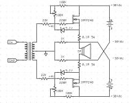
I built something like this. Today I would use 24 or 36 volts switched power supplies instead of 15 volts like I did back in the day.
The chokes are two (bifilar) windings on a large transformer core. It does not need to be air gapped.
It is basically a Zen/SoZ Circlotron Long Tailed Pair.

Last edited:
- Home
- Amplifiers
- Pass Labs
- The Zenitron