Thanks for the tip. I will try that.How very cool to have that resource handy. Maybe they can measure the parasitic capacitance for you? If not it should be fairly easy to do yourself either by sweeping through the audio frequencies and monitoring the impedance of the choke .or. by wiring up your "1:1 transformer" with the primary as a load and watching the frequency response on the seconday windings. Hopefully, it'll be flat out to at least 80 KHz.
I was a bit tired and forgot to draw it. Ofcourse there is a ground reference point in the middle of the circuir, but the amp works without it.(1) Why did the ground reference disappear from the middle (symetry point) of the circuit?
The input nodes (junktion of 1K and 10K is a virtual ground and the amp will strive to keep the points at zero volts by adjusting the voltage at the speakerterminals to compensate for any dc offset or ac signal.(2) Is the 10K R the feedback? If so, then i assume that as signal appears across the speaker one or another of the input nodes (junction of 1K and 10K) will deviate from 0v. Yes? Without DC blocking caps at the signal imputs, how does that impact the source device's output requirements?
See Mr Pass exelent article about the Zen-amps. The have the same arrangement.
new to this whirling dervish
That helps... this whirling currents thing is new to me so i appreciate your pointers to get me spinning in the right direction. Are there any concerns about what happens at that node in the case of a device (FET) failure? I suppose the same question could be asked about the speaker nodes too.
Cheers,
LarryO
Circlomanen said:The input nodes (junktion of 1K and 10K is a virtual ground and the amp will strive to keep the points at zero volts by adjusting the voltage at the speakerterminals to compensate for any dc offset or ac signal. See Mr Pass exelent article about the Zen-amps. The have the same arrangement.
That helps... this whirling currents thing is new to me so i appreciate your pointers to get me spinning in the right direction. Are there any concerns about what happens at that node in the case of a device (FET) failure? I suppose the same question could be asked about the speaker nodes too.
Cheers,
LarryO
If you look on the last drawing of the circuit you will see that the big coil will short out any current from the speaker if a device fails. The speaker should be safe, depending on the DCR of the coil. mine is only 0,6 ohms so that will save the speaker in the event of devicefailour. The input is protected to some extent by the coil and the 10 K resistor. I unlugged one of the two floting supplies and nothing much happend. There was a bit of noice and 50 mV DC offset across the speaker that was connected. I did not measure the inputs but I had no problem with the headphone-output of my CD player afterwards.That helps... this whirling currents thing is new to me so i appreciate your pointers to get me spinning in the right direction. Are there any concerns about what happens at that node in the case of a device (FET) failure? I suppose the same question could be asked about the speaker nodes too.
Im working on a new uppdated biascircuit now. Im very hopefull it will work fine. I had simmilar problems when I was expermenting with the ZEUS amp a while ago. The amp seems to be unstable at high power output levels so the DC balance drifts and saturates the core of my choke. With a much more stable bias voltage setting that is not dependent of the supply-voltage, the problems should be handled. I will probably use a couple of zeners that I buffer with a couple of small transistors to make it stable.
🙂 Thanks. I hope someone else will try this amp someday.Great stuff, Circlomanen!
The last version with the new updated biascircuitry and ground connection.
An externally hosted image should be here but it was not working when we last tested it.
Since I realy hate added complexity, im not realy happy about the solution above......
Im trying to figure out a way to make it more stable without using a lot of extra devices,resistors and whatever...
Any solutions, thoughts,comments?????
Im trying to figure out a way to make it more stable without using a lot of extra devices,resistors and whatever...
Any solutions, thoughts,comments?????
simplified bias reg?
If the bias voltage regulator circuit does not need to handle more than 15 mA, you might have a look at the LM4040. It's a precision, low noise, shunt regulator. Might help eliminate a half dozen components.
Cheers,
LarryO
Circlomanen said:Since I realy hate added complexity, im not realy happy about the solution above......
Im trying to figure out a way to make it more stable without using a lot of extra devices,resistors and whatever...
Any solutions, thoughts,comments?????
If the bias voltage regulator circuit does not need to handle more than 15 mA, you might have a look at the LM4040. It's a precision, low noise, shunt regulator. Might help eliminate a half dozen components.
Cheers,
LarryO
Thanks!! I will look into that. Seems like a simple solution.If the bias voltage regulator circuit does not need to handle more than 15 mA, you might have a look at the LM4040. It's a precision, low noise, shunt regulator. Might help eliminate a half dozen components.
Thanks Tom2!
That is one easy solution I have missed. That way its easy to build a simple Zenitron without the big centertapped choke. Just use a input transformer and two ground reference points!
The most simple Zenitron yet! Thanks!🙂
Thank you Tom2!!!IMHO the difficulty I am having understanding the zenitron, SuSy circlotron circuits and x100 circuit is the circuits seem to need or have two or more ground reference points. My brain keeps telling me the circuits can have only one?????
I can't get it through my brain on how to drive a circlotron with volatage gain in a balanced way without resorting to input transformers as a way to isolate the two circlotron halves from having ground reference problems. Maybe I just don't see it yet.
That is one easy solution I have missed. That way its easy to build a simple Zenitron without the big centertapped choke. Just use a input transformer and two ground reference points!
The most simple Zenitron yet! Thanks!🙂
Circlomanen,
Your welcome.
How about using more than one circlotron in a circuit.
Cascodatron???
Tom
Your welcome.
How about using more than one circlotron in a circuit.
Cascodatron???
Tom
The QUADITRON was a try at that. Im working on some extremly complex versions with multiple ouput transformars and chokes. I dont know if it ever will become anything usefull, but its always fun thinking about something.Tom2 said:Circlomanen,
Your welcome.
How about using more than one circlotron in a circuit.
Cascodatron???
Tom
Circlomanen,
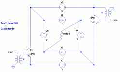
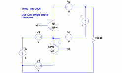
Here are two ideas for your enjoyment.
Yes I agree, multiple circlotrons get very confusing.
The cascodraton idea (or whatever you want to call it) sometimes makes sense and other times seems completely wrong to me.
One could have complementary inner devices or currents rotating in the same or opposite directions. Connections between the different circlotrons.......?????
Have fun!
Tom
Attachments
Tom2 said:One could have complementary inner devices or currents rotating in the same or opposite directions. Connections between the different circlotrons.......?????
Tom
When a dextro (clockwise) rotating circlotron hooks up with a levo (counterclockwise) rotating circlotron, does one get no sound or infinite sound? Will it have to be aligned with the earth's magnetic field?
Just curious,
LarryO
Not only infinite or null sound. It will have an infinite dynamic range. From negativ infinity to positive infinity with a pivotpoint at zero.lgo51 said:
When a dextro (clockwise) rotating circlotron hooks up with a levo (counterclockwise) rotating circlotron, does one get no sound or infinite sound? Will it have to be aligned with the earth's magnetic field?
Just curious,
LarryO
It will shift earths magnetic field 180 degrees back and forth to even out the magnetic parasite-currents in the output devices.
Great subwoofer amp. It will truely rock the earth.😀
Circlomanen said:It will shift earths magnetic field 180 degrees back and forth to even out the magnetic parasite-currents in the output devices.
Great subwoofer amp. It will truely rock the earth.😀
Nooooooooo.... not hip-hop goes geo-rock 😱
When a dextro (clockwise) rotating circlotron hooks up with a levo (counterclockwise) rotating circlotron, does one get no sound or infinite sound? Will it have to be aligned with the earth's magnetic field?
My only concern would be hybrid cyborg-humans showing up from the future claiming such a circuit is decompactifying and exciting the 8th, 9th and 10th dimensions creating 3-branes thus causing mini big-bangs to randomly occur in the future.
Tom
😀Tom2 said:
My only concern would be hybrid cyborg-humans showing up from the future claiming such a circuit is decompactifying and exciting the 8th, 9th and 10th dimensions creating 3-branes thus causing mini big-bangs to randomly occur in the future.
Tom
THAT is the hardest part of Circlotron design. The cyborgs are hard to negotiate with. They are often hostile and the have all different kinds of flashy weapons. You have to keep a few 40 megaton thermoneuclear bombs laying around to kick their buts.😀
But its worth it! Who would sacrifice infinite dynamic range just because some cyborgs get there future home universe a bit ripped apart???😀
- Home
- Amplifiers
- Pass Labs
- The Zenitron

