Thank you Andréa for the report,what is the supply voltage of the new oscillator,always 6 Volt and 3Volt?
Not yet defined, it's a prototype to be tested and refined.
It's a different design with different power supply, maybe batteries powered.
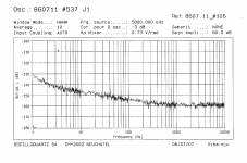
This is the first measurement of the new oscillator prototype with the Laptech SC 3rd overtone crystal at 5.6448 MHz.
The plot compares the phase noise performance of the new oscillator (green plot) against the Crystek CCHD-957 at 22.5792 MHz (blue plot) and a custom made OCXO from HCD at 11.2896 MHz (pink plot).
The Crystek was powered by Lifepo4 battery supply, while the other 2 oscillators was powered by standard regulators (this explains the spurs in the plot).
There is still improvement margin, since the power supply is not the best (to be measured with Lifepo4 batteries), it was measured on the fly in air without any shielding box, there isn't an oven.
Hope this was a Christmas gift.
Andrea
Pretty amazing spec. Well done!
TCD
Looks great. Now I can look forward to buying a Laptech SC 3rd overtone crystal at 5.6448 MHz and putting it into service in 2020. I hope you will do another group buy for the 5.6MHz oscillator.
At clsidxxl, You meant best to use LiPoFe without reg (while not stable volttage value but lowest noise) ?
My experience with Christeq is i have better result with ldo and c cors traffos than LiPo with the best low noise low ppsr LDOs... sonically speaking..
Hey thanks Andrea, nice picture...
My experience with Christeq is i have better result with ldo and c cors traffos than LiPo with the best low noise low ppsr LDOs... sonically speaking..
Hey thanks Andrea, nice picture...
Beautiful measures, Andrea. Much better than the AT-cut results at the first page of the topic.
Sorry to toss some cold water on the measurements but ÷2 in frequency and phase noise drops by 6 dab so making comparisons with widely different frequencies can be misleading. The 5 MHz seems the sweet spot for OXCOs but it needs to be multiplied to be useful. So you need to figure out multipliers or dividers. The Crystek divided may look much better.
Not yet defined, it's a prototype to be tested and refined.
It's a different design with different power supply, maybe batteries powered.
battery powered? integrated battery design? 🙂
super! me gusta la bateria ;-)
Thanks Andrea,you should consider the Supercapacitor power supply,some like 5Volt,it could be done with the UcConditioner of Ian.Not yet defined, it's a prototype to be tested and refined.
It's a different design with different power supply, maybe batteries powered.
diyiggy,i use the SC Cut of Andrea,this one must be feed by 2 different voltage,3,3V and 6V,for the slicer at 3,3V i alternately used 1 Lifpo4 and LT3045 of LDOVR,I did not hear any difference between the two, at least it was not obvious,
I'm waiting for the new design of Andrea,I want to try the Supercap power supply.
______________________________________________
😉Ad Astra 'long course pilot,they look good in their skin.
Andrea, nice result.
May I ask, where did You get access to a Timepod?
What is used as reference?
And it's true that the Crystek looks worse than it really is, because of the frequency.
One should subtract 12dB fron the Crystek values as shown in the graph.
Now the difference is 40dB at 1Hz. After subtraction that will be 'only' 28dB difference, at 1Hz. 😅😆😀
Ciao, George
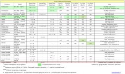
For reference below you can find a comparative table with the best OCXO on the market. The top performers in the range are the Oscilloquartz BVA 8607 and the Wenzel ULN, that means many thousands dollars to get one of these (no chance to get a frequency suitable for digital audio).
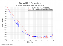
I also attach the phase noise plot of the two top performers. As you can see at 10 Hz from the carrier the phase noise performance of the prototype oscillator is very close to the performance of the best oscillators on the market.
The top performers are better at 1 Hz from the carrier, but as I said in a previous post I think there is still improvement margin by shielding the new oscillator and by feeding it with a better power supply.
It's true that the Crystek is a 22.2792 Mhz oscillator, so you have to divide it by 4 to do a better comparison, and theoretically its phase noise will improve 12dBc, but in the real world I'm not sure you really get 12dBc better phase noise performance. Anyway, assuming 12dBc better, the phase noise difference is 'only' 36 dBc (148.7 - 112).
Attachments
Sorry to toss some cold water on the measurements but ÷2 in frequency and phase noise drops by 6 dab so making comparisons with widely different frequencies can be misleading. The 5 MHz seems the sweet spot for OXCOs but it needs to be multiplied to be useful. So you need to figure out multipliers or dividers. The Crystek divided may look much better.
Hi Demian,
I'll test the oscillator with the Laptech SC crystal at 22.5792Mhz, so we can do a better comparison with the Crystek, anyway scaling the performance by the theoretically 12 dBc, the difference is still huge, almost 36 dBc.
Moreover, the discrete DAC I'm working on with my friend Roberto does not need high frequency oscillators, it will work at 192kHz sample rate with a 6.144 MHz oscillator.
Andrea
At clsidxxl, You meant best to use LiPoFe without reg (while not stable volttage value but lowest noise) ?
My experience with Christeq is i have better result with ldo and c cors traffos than LiPo with the best low noise low ppsr LDOs... sonically speaking..
Hey thanks Andrea, nice picture...
We will test both configuration, linear regulator against LiFePo4 batteries, measurement and listening session.
I will publish the measurement soon, about sonic performance … depending on personal taste.
Andrea, nice result.
May I ask, where did You get access to a Timepod?
What is used as reference?
And it's true that the Crystek looks worse than it really is, because of the frequency.
One should subtract 12dB fron the Crystek values as shown in the graph.
Now the difference is 40dB at 1Hz. After subtraction that will be 'only' 28dB difference, at 1Hz. 😅😆😀
Ciao, George
My development partner and friend Roberto owns a Timepod, so he made the measurement. The references are a couple of MTI OCXO at 5Mhz, but with the cross correlation performed by the Timepod they don't affect much the measurement.
Sorry to toss some cold water on the measurements but ÷2 in frequency and phase noise drops by 6 dab so making comparisons with widely different frequencies can be misleading. The 5 MHz seems the sweet spot for OXCOs but it needs to be multiplied to be useful. So you need to figure out multipliers or dividers. The Crystek divided may look much better.
You are of course right Demian. I normally do a quick 'in my head' compensation calculation.
The sweet spot for this clock is definitely 10Hz offset where it is close to SOTA but either side, mainly phase noise floor is not so good.
Where is schematic for this particular oscillator?
TCD
You are of course right Demian. I normally do a quick 'in my head' compensation calculation.
The sweet spot for this clock is definitely 10Hz offset where it is close to SOTA but either side, mainly phase noise floor is not so good.
Where is schematic for this particular oscillator?
TCD
We are working on a pair of circuits, this one and a new Driscoll based configuration. Let us well test both circuits and then I'll disclose the project.
About the phase noise performance at either side of the 10Hz from the carrier point I think there is margin to improve as I said above. Moreover Roberto made a quick measurement (about 20 minutes) while the top performers were measured for a long time, 8 hours or more. As you know to get the right measurement very close to the carrier (1Hz or less) a long time is needed.
BTW, keep in mind we are comparing a diy oscillator prototype with the best commercial OCXO on the market (and very very expensive).
This is an excellent result Andrea!
I hope you will finish the design soon, my crystals cannot wait to get working!
Please make the ps requirement possible with lifepo batteries; so 3.3v-6.6v-etc.
I hope you will finish the design soon, my crystals cannot wait to get working!
Please make the ps requirement possible with lifepo batteries; so 3.3v-6.6v-etc.
This is an excellent result Andrea!
I hope you will finish the design soon, my crystals cannot wait to get working!
Please make the ps requirement possible with lifepo batteries; so 3.3v-6.6v-etc.
Both oscillators are designed to be supplied with LiFePo4 batteries, the required voltages are anyway multiple of 3V3.
The New Driscoll
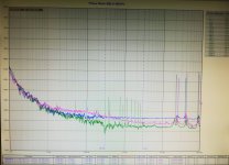
And now the first measurement of the new Driscoll oscillator prototype, without shielding, without oven and powered by linear regulator.
The blue plot is the phase noise of the previous oscillator prototype (crystal drive level around 200uW), while the pink and the green plots are the phase noise of the new Driscoll (drive level 100 and 200 uW).
The previous oscillator is slightly better at 10Hz from the carrier, -152.2 dBc against -146.1 and -148.5 dBc measured for the Driscoll at 100 and 200uW respectively.
On the other side, the Driscoll performs slightly better at both the side of 10Hz from the carrier. On the right side the difference is determined by the circuit, while on the left side we have to wait an accurate measurement once both oscillators are well shielded and powered.
The Laptech SC-Cut 3rd overtone at 5.6448MHz is a truly jewel.
Attachments
Hi Andrea,
This is indeed very interesting and inspiring! ... Looking forward to seeing what you arrive at for a "final version" ...
As you know I am not an expert in this field - yet I reckon that adding the oven, shielding and possibly the batteries may give even better results ... so I can't help but smiling at this ;-)
Merry Christmas Greetings,
Jesper
Hello Andrea,
As I have both the 5 M Hz AT & SC cuts, is it posddible to use the new Discroll board for any with the same BOM (I assume the smallest AT cut size case will ask some legs bending though) ?
If they need more than 3.2V from power supply, do the LiPoFe4 still worth it in serie (I assume you use a smd LDO reg?) ?
cheers
PS : Panettone not yet arrived yet here ! 🙂
- Status
- Not open for further replies.
- Home
- Source & Line
- Digital Line Level
- The Well Tempered Master Clock - Building a low phase noise/jitter crystal oscillator