Hello Andrea,
As I have both the 5 M Hz AT & SC cuts, is it posddible to use the new Discroll board for any with the same BOM (I assume the smallest AT cut size case will ask some legs bending though) ?
If they need more than 3.2V from power supply, do the LiPoFe4 still worth it in serie (I assume you use a smd LDO reg?) ?
cheers
PS : Panettone not yet arrived yet here ! 🙂
Hi,
the new Driscoll is designed to operate with the SC-Cut crystal, you cannot use the AT because it has a very low ESR not suitable for the new circuit.
The AT-Cut crystal at 5.6448MHz works with the old Driscoll circuit only.
About the power supply you can easily use LiFePo4 batteries in series without any problem. BTW, the new Driscoll oscillator will not use LDO, only a little RFI filter.
Andrea
When will you be hink Therese No gain anymore and stop the dBc chase? :
//
No energy to chase the high speed of the "modern Silabs configurable oscillators", I come from the old school and it is already tiring enough to chase the old masters like Wenzel and Oscilloquartz.
Maybe I'm old but not wise.
We must be deaf, my tda1541 dac iw sou xing far bettef than all the diy discreta r2r and ess sabre chips I heard till today....
Anyway i have 4 lipofe cells waiti for the new discroll, low speed will be also my old days....🙂
Anyway i have 4 lipofe cells waiti for the new discroll, low speed will be also my old days....🙂
iw sou xing far bettef discreta waiti will be also my old days....🙂
I think I know what you meant, but did you really meant what you said?
Maybe a crown version would sound even better;-)
Sorry for the Esperanto, lol... bad eyes, little tablett, big fingers and too deaf to use voice with Alexa gadget or alike to write from voice...
But.... I speak the Wookiee...yeah !
But.... I speak the Wookiee...yeah !
Last edited:
Sorry for the Esperanto, lol... bad eyes, little tablett, big fingers and too deaf to use voice with Alexa gadget or alike to write from voice...
It was just funny, sorry for that. My keyboard does tripplle and double L's, extra spaces etc etc, if I'm not payingattention.
Haha;-)
Have a good evening diyiggy!
No energy to chase the high speed of the "modern Silabs configurable oscillators", I come from the old school and it is already tiring enough to chase the old masters like Wenzel and Oscilloquartz.
Maybe I'm old but not wise.
Keep it up :-D !!
Have yet to build my osc from the first GB 🙄
//
Keep it up :-D !!
Have yet to build my osc from the first GB 🙄
//
Me too...
Maybe I am old but not wise 😎
BTW (small off...)
Andrea,
I was by chance tried 4R-R discrete dac ladder network. Connected as start, like 2 blocks as ballanced with +Data, and -Data. I feed both blocks with same data and make "single ended" 4R/1R network. Somehow I like the sound more?
Andrea,
I was by chance tried 4R-R discrete dac ladder network. Connected as start, like 2 blocks as ballanced with +Data, and -Data. I feed both blocks with same data and make "single ended" 4R/1R network. Somehow I like the sound more?
Hi,
I haven't been following this thread in a very long time, my question might be redundant/simple, but I figured I might ask anyway. The question is about the Clapp Oscillator schematic (as posted in #9 by andrea_mori in this thread).
In the schematics power supply there are decoupling capacitors and ferrite beads used for EMI suppression. This seems like a great idea, but wouldn't they also form a resonance circuit?
If I simulate this in LTspice with typical DCR of a ferrite bead (300mOhm to 600mOhm) I get a Q of about 9 and a resonance frequency of 33.9kHz (L=22uH, C=1uF, R=500mOhm).
I would think that adding an additional RC-snubber network in parallel with the capacitor would help with reducing the Q of the EMI filter.
Also, Merry christmas everyone!
Most of the jitter is due to broadband phase noise, ie the noise floor of the oscillator, not the close-in phase noise. Close-in phase noise is important for some RF applications, and test-gear, but not for driving an ADC or DAC, where rms jitter is what affects performance.
https://www.analog.com/media/en/training-seminars/tutorials/MT-008.pdf
https://www.analog.com/media/en/training-seminars/tutorials/MT-008.pdf
Most of the jitter is due to broadband phase noise, ie the noise floor of the oscillator, not the close-in phase noise. Close-in phase noise is important for some RF applications, and test-gear, but not for driving an ADC or DAC, where rms jitter is what affects performance.
https://www.analog.com/media/en/training-seminars/tutorials/MT-008.pdf
I understand that the majority of the jitter is due to broadband noise and 1/f noise. However that is random noise. There are also instances where the noise is not random due to magnetic/capacitive coupling or power supply noise.
If one would add an additional sensitivity to power supply noise (by LC style decoupling) wouldn't that be a bad thing? As far as I understand power supply noise (non-random) would cause AM-modulation and represent itself in the phase noise plot at peaks.
Most of the jitter is due to broadband phase noise, ie the noise floor of the oscillator, not the close-in phase noise. Close-in phase noise is important for some RF applications, and test-gear, but not for driving an ADC or DAC, where rms jitter is what affects performance.
https://www.analog.com/media/en/training-seminars/tutorials/MT-008.pdf
In digital to analog conversion you have to look to the RMS Phase Jitter, that's mostly affected by the close-in phase noise.
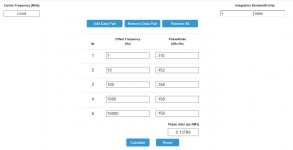
Please, take a look at the attached pictures.
The first shows the phase noise to jitter conversion of phase noise plot of the first measured prototype oscillator. As you can see the calculated RMS phase jitter is around 138 femto seconds.
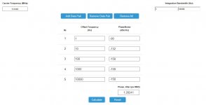
The second picture shows the same plot with some alterations of the close-in phase noise, +20dBC at 1Hz and 10Hz from the carrier. As you can see the RMS jitter rises to 1.282 pS.
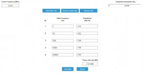
Now the third pictures that shows the same plot but with different alterations, +20dbC at 100Hz, 1000Hz and 10000Hz from the carrier. Also in this case the RMS phase jitter rises to 516 fS, but much less than in the previous alteration of the close-in phase noise.
Attachments
So if I understand you correct, you don't care about the added noise due to the resonance, because the signals are in the 30-40kHz range and have relatively little impact on the rms jitter?
So if I understand you correct, you don't care about the added noise due to the resonance, because the signals are in the 30-40kHz range and have relatively little impact on the rms jitter?
No, I only said that the major impact on the RMS Phase Jitter is the close-in phase noise, then all the broadband noise affects the RMS Jitter and should be limited anyway.
No, I only said that the major impact on the RMS Phase Jitter is the close-in phase noise, then all the broadband noise affects the RMS Jitter and should be limited anyway.
Then if I may ask, why is it that the resonance of the ferrite bead and the decoupling capacitor is not damped? Wouldn't it add sensitivity to noise since the Q is about 9 at ~33.9kHz?
Am I perhaps modelling a ferrite bead wrong? I model it like an ideal inductor with about 500mOhm series resistance and about 1k parallel resistance.
And now the first measurement of the new Driscoll oscillator prototype, without shielding, without oven and powered by linear regulator.
Hi Andrea,
truly amazing!
1Hz phase noise will certainly improves with shielding, phase noise doesn't like airflow...
Joël
Hi Andrea,
truly amazing!
1Hz phase noise will certainly improves with shielding, phase noise doesn't like airflow...
Joël
Thanks Joel, we are very satisfied for the excellent phase noise performance reached with the new oscillators.
But I have to say that Laptech crystals are the treasure.
We are working on more projects, for example we are developing a new audiophile asynchronous FIFO buffer
https://www.diyaudio.com/forums/dig...-buffer-slaved-i2s-reclocker.html#post6044362
And also: LiFePo4 battery supply, discrete DACs and so on.
Coming soon.
https://www.diyaudio.com/forums/dig...-buffer-slaved-i2s-reclocker.html#post6044362
And also: LiFePo4 battery supply, discrete DACs and so on.
Coming soon.
- Status
- Not open for further replies.
- Home
- Source & Line
- Digital Line Level
- The Well Tempered Master Clock - Building a low phase noise/jitter crystal oscillator