Supersurfer
What is your value for R2 & R7. Should be 1k. Not sure if I am reading your part correctly? looks like 100r?
Walter
What is your value for R2 & R7. Should be 1k. Not sure if I am reading your part correctly? looks like 100r?
Walter
Hi both ...
I think R2 and R7 are correct. 102 both reads which is 1000. Could also be 200 but I reckon this is not likely ;-) ... The only ideas I get is if you have checked all the via plate throughs for connection; if R3 and R5 may be interchanged (no values shown - same color); or if the IC may be rotated 180 degrees. Otherwise I have no further suggestions ...
Jesper
The resistors are the correct value. Also the blue ones are on the correct spot. I keep all components in the labeled mouser bags and take them out one by one while soldering. The ic has the same orientation as on the other pcb (that is regulating correctly).
I was thinking that I might have some shorts due to solder flux sitting below the components but when measuring the resistors there is no indication of a short. The pcb is cleaned with alcohol.
I was thinking that I might have some shorts due to solder flux sitting below the components but when measuring the resistors there is no indication of a short. The pcb is cleaned with alcohol.
Just checking: you have used "normal" solder to splder the parts on the board?
E.g. bismuth based solder melts at around 180 degrees C, if you did use that and the parts get really hot it's easy to desolder.
E.g. bismuth based solder melts at around 180 degrees C, if you did use that and the parts get really hot it's easy to desolder.
have you checked R5? Is it possible the left side not connecting to the pad?
Otherwise everything looks fine from the pic.
Thanks Jesper. I never realized how the 3 digit marking on the resistor works. Learn something new every day.
Otherwise everything looks fine from the pic.
Thanks Jesper. I never realized how the 3 digit marking on the resistor works. Learn something new every day.
Check rather R4, as the component is bigger than the pad itself. It is hard to solder it properly in this situation.have you checked R5? Is it possible the left side not connecting to the pad?
Otherwise everything looks fine from the pic.
Thanks Jesper. I never realized how the 3 digit marking on the resistor works. Learn something new every day.
The resistor shall be one physical size smaller. (0805 instead of 1206)
Good point. Tough to do this without a hot air station.Check rather R4, as the component is bigger than the pad itself.
Just checking: you have used "normal" solder to splder the parts on the board?
E.g. bismuth based solder melts at around 180 degrees C, if you did use that and the parts get really hot it's easy to desolder.
I used smd solder flux, no low temperature solder. The input resistor gets really hot that is why I took it off.
I changed the sensing resistor for a new one, still running hot.
I will double check the resistors.
Regards,
Due to high temperature, some of the components may failed. To my surprise, I got a broken R2 after 2 years of operation (7/24). Others, like OP amp, BJT, Regulator...etc are fine.
@Andrea, is there any news on the development of the clock boards for the bigger sc-cut crystals?
I have a pair of crystals waiting to go into service anxiously 🙄
Ps. I still have not found time and the energy to solve my oven problem 🙁
I have a pair of crystals waiting to go into service anxiously 🙄
Ps. I still have not found time and the energy to solve my oven problem 🙁
@Andrea, is there any news on the development of the clock boards for the bigger sc-cut crystals?
I have a pair of crystals waiting to go into service anxiously 🙄
Ps. I still have not found time and the energy to solve my oven problem 🙁
PCB prototype is on the way.
Let me know about the oven as soon as you do more test.
PCB prototype is on the way.
Let me know about the oven as soon as you do more test.
I will keep you updated.
I am very curious of your new pcb’s!
Regards,
PCB prototype is on the way.
Any update?
Maybe a christmas present for us? 😀
Any update?
Maybe a christmas present for us? 😀
Time for testing, please be patient and stay tuned!
Andrea
Hi G600,
With the strokes you have you wouldn't have it for Christmas anyway. 😀
Keep the good job Andrea, take the time you need and thank you again for sharing .... 🙂
With the strokes you have you wouldn't have it for Christmas anyway. 😀
Keep the good job Andrea, take the time you need and thank you again for sharing .... 🙂
Hi Andrea (& All),
Wishing you a Merry Christmas - and really looking forward to hearing what you have arrived at with the oscillators (and still a many, many thanks for doing this & sharing it!) ...
Cheers,
Jesper
Wishing you a Merry Christmas - and really looking forward to hearing what you have arrived at with the oscillators (and still a many, many thanks for doing this & sharing it!) ...
Cheers,
Jesper
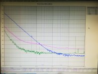
When the crystal makes the difference
This is the first measurement of the new oscillator prototype with the Laptech SC 3rd overtone crystal at 5.6448 MHz.
The plot compares the phase noise performance of the new oscillator (green plot) against the Crystek CCHD-957 at 22.5792 MHz (blue plot) and a custom made OCXO from HCD at 11.2896 MHz (pink plot).
The Crystek was powered by Lifepo4 battery supply, while the other 2 oscillators was powered by standard regulators (this explains the spurs in the plot).
There is still improvement margin, since the power supply is not the best (to be measured with Lifepo4 batteries), it was measured on the fly in air without any shielding box, there isn't an oven.
Hope this was a Christmas gift.
Andrea
Attachments
Thank you Andréa for the report,what is the supply voltage of the new oscillator,always 6 Volt and 3Volt?
Last edited:
- Status
- Not open for further replies.
- Home
- Source & Line
- Digital Line Level
- The Well Tempered Master Clock - Building a low phase noise/jitter crystal oscillator