heating components
Hi Supersurfer
It has crossed my mind that I tempted you out of happily listening to a good set up to days of frustration with the oven. Sorry for that🙂
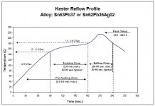
Just reminding myself of the heating profile for smt solder reflow, I think you can safely take the entire board up to 85C for several minutes without expectation of damage. The parts are expected to heat soak for 2-4mins at up to 180C, so presumably under 100 should be fine for a couple of minutes. I have followed this profile using a toaster oven for larger builds without damage to parts. Sounds like your failure mode is constantly at around 1min. If you view hot air station how to video, you see a process of kind of waving the hot air back and forth without heating one spot. Perhaps the same technique with a hair blower could allow you to heat the entire pcb up to around 80c for a couple minutes. Practice with a junk pcb before hitting the WTMC.
It will also allow you to hear impact of the oscillator around it's happy temp.
Seemed like Andrea was pointing to oscillation in the 12v reg, but good to eliminate heat as a variable. Seems like a stretch but maybe something went wrong when you were removing and replacing the inductor.
Hi Supersurfer
It has crossed my mind that I tempted you out of happily listening to a good set up to days of frustration with the oven. Sorry for that🙂
Just reminding myself of the heating profile for smt solder reflow, I think you can safely take the entire board up to 85C for several minutes without expectation of damage. The parts are expected to heat soak for 2-4mins at up to 180C, so presumably under 100 should be fine for a couple of minutes. I have followed this profile using a toaster oven for larger builds without damage to parts. Sounds like your failure mode is constantly at around 1min. If you view hot air station how to video, you see a process of kind of waving the hot air back and forth without heating one spot. Perhaps the same technique with a hair blower could allow you to heat the entire pcb up to around 80c for a couple minutes. Practice with a junk pcb before hitting the WTMC.
It will also allow you to hear impact of the oscillator around it's happy temp.
Seemed like Andrea was pointing to oscillation in the 12v reg, but good to eliminate heat as a variable. Seems like a stretch but maybe something went wrong when you were removing and replacing the inductor.
Attachments
Last edited:
Hi wealas,
The small plastic is inserted below the crystal. I do not know it’s purpose; electrical or heat isolation to the board?
Wlowes,
Your summary of my problem is correct.
It’s a good idea to try to heat the crystal without the oven in order to close out causes. I think this is a difficult task; using a hot air gun or hair blower will provide an overdose of hot air that will be impossible to direct to the crystal without overheating the other components. I do not own an air soldering device.
After your report of getting a clearly better sound when using the oven, I am even more frustrated that it does not function in my case. 🙁
There must be an explanation why it is not functioning, I hope Andrea can shed some light in the matter.
Do you own an oscilloscope?
I have an old 35mhz oscilloscope but dislocated the probes during moving to a new house.
But I did receive my temperature probe and ran some tests!
The temperature was stabilising around 94degrees and the clock lock dropped around 2 minutes.
After re-adjustment I got it down to 83degrees. also clock lock dropped but I did not check the duration.
Next I fixed the temp. probe to the crystal with a piece of copper and a tie wrap, the extra piece of copper caused the temperature to stabilise at around 76degrees.
I made a short film of this test. The clock kept locked for around 4 minutes on the fifopi, so everything looked ok. Than I adjusted the temp. and you can hear the music stop and see the led indicating clock lock on the fifopi switching. I assume the frequency of the clock changed at that moment due to my interference (vibration or so).
YouTube
The first 3 minutes are speeded up, around 1:00 you can hear the music stop and see the fifopi switching to the other clock.
I have an old 35mhz oscilloscope but dislocated the probes during moving to a new house.
But I did receive my temperature probe and ran some tests!
The temperature was stabilising around 94degrees and the clock lock dropped around 2 minutes.
After re-adjustment I got it down to 83degrees. also clock lock dropped but I did not check the duration.
Next I fixed the temp. probe to the crystal with a piece of copper and a tie wrap, the extra piece of copper caused the temperature to stabilise at around 76degrees.
I made a short film of this test. The clock kept locked for around 4 minutes on the fifopi, so everything looked ok. Than I adjusted the temp. and you can hear the music stop and see the led indicating clock lock on the fifopi switching. I assume the frequency of the clock changed at that moment due to my interference (vibration or so).
YouTube
The first 3 minutes are speeded up, around 1:00 you can hear the music stop and see the fifopi switching to the other clock.
Summarizing:
- with the oven at a temp around 76°C the oscillator starts and works properly
- then if you set the temp to 83°C the oscillator locks
- without the oven the oscillator starts and works correctly
Do you confirm?
Andrea
Yes, until I touch the board or crystal.Summarizing:
- with the oven at a temp around 76°C the oscillator starts and works properly
Yes- then if you set the temp to 83°C the oscillator locks
- without the oven the oscillator starts and works correctly
Yes, without the oven it works all the time without any hickups.
With the oven on it either locks by itself or by a slight external movement like touching the krystal with a temp. Probe or adjusting the temp on the multiturn resistor.
Yes, until I touch the board or crystal.
Yes
Yes, without the oven it works all the time without any hickups.
With the oven on it either locks by itself or by a slight external movement like touching the krystal with a temp. Probe or adjusting the temp on the multiturn resistor.
Have you placed the insulator tab between the crystal and the board?
Yes, I did.Have you placed the insulator tab between the crystal and the board?
Yes, I did.
The first thing to do is to check if the regulator of the oven oscillates using an oscilloscope.
If you cannot use an oscilloscope you can try using a DMM. Power up the oven only then apply a DMM between the output of U1 and ground. Set the DMM to AC mode and check if there is any voltage.
The first thing to do is to check if the regulator of the oven oscillates using an oscilloscope.
If you cannot use an oscilloscope you can try using a DMM. Power up the oven only then apply a DMM between the output of U1 and ground. Set the DMM to AC mode and check if there is any voltage.
Hi Andrea,
I measured the ac on 7812 output; the Fluke DMM only displays a stable 0,002VAC. To me this seems not an indication for oscillation but I can be mistaken.
the AC on the transistor output is fluctuating between 0,002-0,024VAC. I do not know if this is ok, maybe just regulating the temp. This is measured after heating for +15min.
Maybe nothing to do with the current issue I have but I did notice a possible problem at starting up: the inrush current is so high at startup that the input voltage sags to below 12v after the 10r resistor and the 7812 output is on 9V, this goes up after a while and stabilises to 16,41v before 10r, 14,4v before 7812 and 11,95v after 7812. Total current draw after stabilising is 200mA
Whith the high inrush current the solderings of the 10r resistor melt!
This cools down after a minute but I expect this will raise problems with bad soldering connection after a while. Is this resistor mandatory? I use a stabilised ps with LT1083.
Do you have any other thoughts on the issue?
Regards,
Hi Supersurfer,
I'm sorry I don't really have a suggestion as to what can be amiss here ... One "likely unlikely" thing is that the 7812 has a drop-out voltage of 2-2.5 volts - but yours is at 2.45 volts so I would not assume that this was the issue.
About the 10R resistor I am not familiar with whether or not the 7812 has HF instability issues - but the 10R + 330nF capacitor gives a cut-off frequency of appr. 48 kHz ...
One thought - you don't by any chance have access to spare semiconductors so that you may replace the U1, U2 and Q1? Just an idea ...
@Andrea: I know that you are redesigning things for a V2 - and this may also include the OVN circuitry - but in case the inrush current is this high, and the 10R resistor is still in the circuit, might it then be a solution to use an LM317T instead with a current-limiting circuitry similar to the figure bottom left on p. 20 in the attached datasheet?
Cheers,
Jesper
Attachments
Hi Andrea,
I measured the ac on 7812 output; the Fluke DMM only displays a stable 0,002VAC. To me this seems not an indication for oscillation but I can be mistaken.
the AC on the transistor output is fluctuating between 0,002-0,024VAC. I do not know if this is ok, maybe just regulating the temp. This is measured after heating for +15min.
Maybe nothing to do with the current issue I have but I did notice a possible problem at starting up: the inrush current is so high at startup that the input voltage sags to below 12v after the 10r resistor and the 7812 output is on 9V, this goes up after a while and stabilises to 16,41v before 10r, 14,4v before 7812 and 11,95v after 7812. Total current draw after stabilising is 200mA
Whith the high inrush current the solderings of the 10r resistor melt!
This cools down after a minute but I expect this will raise problems with bad soldering connection after a while. Is this resistor mandatory? I use a stabilised ps with LT1083.
Do you have any other thoughts on the issue?
Regards,
From the AC measurement it looks like that the regulator is not oscillating. 200 mA is the ordinary current consumption as soon as the oven reaches the working temperture. Also, the 10R resistor works correctly, since the voltage drops around 2 volt, from 16.41V before the resistor to 14.4V after the resistor (200 mA * 10R = 2 volt).
What is abnormal is that the solderings of the 10R resistor getting melted, I have never observed this situation. Obvously the 10R resistors runs hot at startup because of the inrush current when the oven is cold, but I have never seen the solderings melt.
The 10R resistor acts as a low pass filter with the 0.33 uF capacitor, you can remove it but you need to decrease the input voltage from 16 to 13-14 volts, absolutely not more than 14 volts, otherwise you burn the regulator and/or the transistor.
But before removing the 10R resistor I would try the update I have suggested in post #1843 (replacing C1, C2 and evenctually C3).
IMHO, since there is no oscillation in the oven I think there is a ground loop issue.
@gentlevoice
Thanks for the suggestion about the regulator, but if the new Driscoll oscillator will need a oven it will be totally different.
From the AC measurement it looks like that the regulator is not oscillating. 200 mA is the ordinary current consumption as soon as the oven reaches the working temperture. Also, the 10R resistor works correctly, since the voltage drops around 2 volt, from 16.41V before the resistor to 14.4V after the resistor (200 mA * 10R = 2 volt).
What is abnormal is that the solderings of the 10R resistor getting melted, I have never observed this situation. Obvously the 10R resistors runs hot at startup because of the inrush current when the oven is cold, but I have never seen the solderings melt.
The 10R resistor acts as a low pass filter with the 0.33 uF capacitor, you can remove it but you need to decrease the input voltage from 16 to 13-14 volts, absolutely not more than 14 volts, otherwise you burn the regulator and/or the transistor.
But before removing the 10R resistor I would try the update I have suggested in post #1843 (replacing C1, C2 and evenctually C3).
IMHO, since there is no oscillation in the oven I think there is a ground loop issue.
Hi Andrea,
Thanks for the suggestions. I have first added the caps to C1 and C2, this made no difference, also adding a 0,47uf film cap to C3 did not help.
The clock still drops out after a few minutes warming up the oven.
I have not removed the r10 resistor yet, I will do this just to be safe but I do not think it will solve the drop-out problems.
Hi,
it seems that as soon as the oven has reached the nominal temperature the frequency of the oscillator was shifted, difficult to say without an oscilloscope.
BTW, have you tried with 48x materials? have you the same issue with both sample rate families 44.1x and 48x?
Have you tried any other source with these oscillators?
Andrea
I have not started building the 48x oscillator yet. I am now building a second oven to see if it has the same behavour.
It is not 100% clear what you mean with “other source”
I have used the oscillator with two different streamer/dacs (but both with a raspberry pi with fifopi) they have the same behavour.
I also used two different (but the same type) regulated power supply for the oven. Same behavour.
Regards,
I do not seem to have much luck.
On the test bench the oven, when switched on, runs up to 160degC, than the 7812 drops from 12v down to 4v out; too much current. I also noticed that R1 becomes way too hot (hotter than on my other oven) so I removed it.
What can be the problem? Is Q1 or U2 defective?
On the test bench the oven, when switched on, runs up to 160degC, than the 7812 drops from 12v down to 4v out; too much current. I also noticed that R1 becomes way too hot (hotter than on my other oven) so I removed it.
What can be the problem? Is Q1 or U2 defective?
Shooting in the dark... I wonder if it is somehow seeing a short and 7812 is going into thermal shutdown. Seems improbable that two sets of parts would both be defective. But in my case I could easily repeat the same assembly error on 2 boards. Suggest you post a pic of your finished oven in case a fresh set of eyes can spot something amiss. I know its a long shot...I do not seem to have much luck.
On the test bench the oven, when switched on, runs up to 160degC, than the 7812 drops from 12v down to 4v out; too much current. I also noticed that R1 becomes way too hot (hotter than on my other oven) so I removed it.
What can be the problem? Is Q1 or U2 defective?
@Supersurfer: I am also guessing here ... but just to make sure: You have bought/used exactly the components in the BOM - and the 5k NTC resistor (R3) is the right one - and it is not defective/it is mounted correctly? If it is defective that might explain why the feedback loop could continue to pump out current, in order to try to increase the temperature.
Cheers,
Jesper
Cheers,
Jesper
Agreed Gentlevoice… I figured either a problem with the variable resistor (solder) or the op amp in the wrong orientation. It is consistent with the initial observation that it was not possible to dial in the desired temperature.
Agreed Gentlevoice… I figured either a problem with the variable resistor (solder) or the op amp in the wrong orientation. It is consistent with the initial observation that it was not possible to dial in the desired temperature.
Hi Wlowes, Jesper,
I bougth 2 oven pcb’s and the components for 4 oven boards in order to have some spares.
Only some resistors were not available in the exact article number at mouser but they are the same value, size and type though.
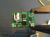
The current sensing resistor could be defective, I will replace this one for a new one.
Maybe you can spot a defect on the attached picture.
Attachments
- Status
- Not open for further replies.
- Home
- Source & Line
- Digital Line Level
- The Well Tempered Master Clock - Building a low phase noise/jitter crystal oscillator