@1audio, gerhard, alexiss, herbert ... if possible ...
Hi all ;-)
I'm in the process of selecting components for a 6.144 MHz version with a divider so that the 6.144 MHz may be divided to a lower frequency. To this end - and considering the comments there's been in relation to the HC04/HCU04/other slicers - I am curious as to the selection of an FF for division? Would you choose the potatosemi (PO74G74A), the LVC (SN74LVC74), or ?? versions for a 4 VDC supply FF divider?
Thanks for any input ;-)
Jesper
Last edited:
Me too - thank you. Can't wait for the driver boards!
Best wishes and thank you for all the hard work.
With admiration,
Simon
Best wishes and thank you for all the hard work.
With admiration,
Simon
Folks, some tips for everyone
for example, if we wanna buy a 10M clock, all we do is looking for the phase noise under 1kHz, cos the frequency bigger than 1kHz in here is kinda none sense.
The important key is the noise at 1Hz, some are -120 dBc@1Hz, that's pretty good already.
for example, if we wanna buy a 10M clock, all we do is looking for the phase noise under 1kHz, cos the frequency bigger than 1kHz in here is kinda none sense.
The important key is the noise at 1Hz, some are -120 dBc@1Hz, that's pretty good already.
TWTMC-P: the Pierce oscillator was born
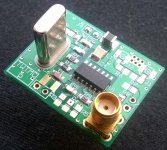
The Pierce oscillator board was build and tested. It's the simplest oscillator presented on this thread, since it uses unbuffered inverters only. It's suitable for AT-Cut crystals only.
Although the Pierce oscillator works from 5 MHz up to 100 MHz, for frequencies above 25 MHz it's not recommended. At these frequencies overtone crystals are used, the ESR increases a bit, so the TWTMC-D Driscoll oscillator is strongly recommended.
Attached the finished 11.2896 MHz Pierce oscillator board.
Attachments
Updated schematics, PCBs, BOMs and Assembly guide
Attached the assembly guides of all the boards available. They contain the schematic of each board, the BOM to source the parts and the instructions to build each circuit.
Some components value of the TWTMC-D Driscoll oscillator have been revised, since with the previous values the power dissipated in the crystals was too high. Frequencies interested are 11.2896 MHz, 22.5792 MHz and 24.576 MHz.
- TWTMC-C: Colpitts-Clapp oscillator revised
- TWTMC-D: Driscoll oscillator revised
- TWTMC-P: Pierce oscillator
- TWTMC-D&D: daughter board (power supply, dividers, and so on) revised to supply the Driscoll oscillator and the oven board
- TWTMC-OVN: oven board for SC-Cut crystals Driscoll oscillator
- TWTMC-DIL: DIL adapter for Ian's Fifo board
Attachments
Hi Andrea,
Just received notice in my mailbox that you had posted these two messages - I assume you are then back from your vacation ... ?
I've now taken a look at the Pierce oscillator and besides looking at the schematic and other information I'm also slightly in awe when considering the options that are now becoming available - three different oscillators each with their merits in different areas .. Thanks Andrea ;-)
As it is the Pierce oscillator appeals to me due to its simplicity ... have you had a chance to actually assess its performance by now - how it performs in terms of phase noise spectrum? I have read earlier that you have limited access to a phase noise measurement device - maybe you've had a chance to look at its phase noise spectrum relative to the other options?
I'm currently underways with making the 6.144 MHz Clapps oscillator but would prefer to use the Pierce if it's comparable with the Clapps for this frequency ...
Cheers,
Jesper
Hi Andrea,
Just received notice in my mailbox that you had posted these two messages - I assume you are then back from your vacation ... ?
I've now taken a look at the Pierce oscillator and besides looking at the schematic and other information I'm also slightly in awe when considering the options that are now becoming available - three different oscillators each with their merits in different areas .. Thanks Andrea ;-)
As it is the Pierce oscillator appeals to me due to its simplicity ... have you had a chance to actually assess its performance by now - how it performs in terms of phase noise spectrum? I have read earlier that you have limited access to a phase noise measurement device - maybe you've had a chance to look at its phase noise spectrum relative to the other options?
I'm currently underways with making the 6.144 MHz Clapps oscillator but would prefer to use the Pierce if it's comparable with the Clapps for this frequency ...
Cheers,
Jesper
Hi Jesper,
yes, back from the vacation last week. Nice trip in the South-West of the USA, about 7.500 km. My favourite is Utah lands, colorful and spectacular.
About phase noise testing limited access means one time only, so it's not yet the time to go because I have to design and test firstly the last oscillator of the group, the Butler two emitters.
The Pierce is claimed to be the best at lower frequency, below 20 MHz. BTW, with the Laptech 6.144 MHz crystal, with its very very high Q, I would suggest the Driscoll oscillator, since it guarantees the higher in circuit loaded Q.
Andrea
Thanks Andrea ;-)
Hmmm ... I hope I can say this in an entirely positive air - but sensing between the lines I somehow note/observe/sense that you have been off on vacation. It's like there's a fresh sense of air or atmosphere - and it's not just related to you - but to most every person I meet who have been on (a fine) vacation. Time to take a vacation I think.
Different, yet in a somewhat parallel direction: My sister has just given birth to a daughter and witnessing how she has changed from being her "one aspect" when at work and being her "second aspect" prior to birth and following birth is a bit perplexing - a quite changed person with more time and attention. Danes - as you might know? - are fortunate in having altogether 9 months paid maternity leave with an additional 3 months (to my memory) on social welfare. Some time to relax - maybe except for the children ...
And then thanks for the feedback on oscillator choice. I will consider which one to use.
Cheers,
Jesper
Hmmm ... I hope I can say this in an entirely positive air - but sensing between the lines I somehow note/observe/sense that you have been off on vacation. It's like there's a fresh sense of air or atmosphere - and it's not just related to you - but to most every person I meet who have been on (a fine) vacation. Time to take a vacation I think.
Different, yet in a somewhat parallel direction: My sister has just given birth to a daughter and witnessing how she has changed from being her "one aspect" when at work and being her "second aspect" prior to birth and following birth is a bit perplexing - a quite changed person with more time and attention. Danes - as you might know? - are fortunate in having altogether 9 months paid maternity leave with an additional 3 months (to my memory) on social welfare. Some time to relax - maybe except for the children ...
I'm not familiar with Utah but just googled some pictures. Indeed spectacular ... & grandios also comes to my mind. Slightly envious I am ... ;-)My favourite is Utah lands, colorful and spectacular.
And then thanks for the feedback on oscillator choice. I will consider which one to use.
Cheers,
Jesper
Hi Andrea nice to hear you are back from vacation.
Got a question about Driscoll oscillator thou. Can we use +5V instead of +6V for the xtal circuit?
Got a question about Driscoll oscillator thou. Can we use +5V instead of +6V for the xtal circuit?
Hi Andrea nice to hear you are back from vacation.
Got a question about Driscoll oscillator thou. Can we use +5V instead of +6V for the xtal circuit?
It works with +5V, a little lower dissipation in the crystal and a little lower loaded Q.
Anyway you should use two separate rails for oscillator and squarer.
Thanks Andrea. I was asking because I got a few pieces of ADM7150 +3.3V and +5V regulator in 78XX footprint I want to utilize, but ADM7150 itself only got fixed voltage up to +5V. Can I connect +7V to Vin on the clock board for both +5V and +3.3V regulators (+5V for xtal, +3.3V for squarer) or still recommended to use separate rails?
Any downside on using +5V for xtal? Will the components value need to change accordingly?
Any downside on using +5V for xtal? Will the components value need to change accordingly?
Thanks Andrea. I was asking because I got a few pieces of ADM7150 +3.3V and +5V regulator in 78XX footprint I want to utilize, but ADM7150 itself only got fixed voltage up to +5V. Can I connect +7V to Vin on the clock board for both +5V and +3.3V regulators (+5V for xtal, +3.3V for squarer) or still recommended to use separate rails?
Any downside on using +5V for xtal? Will the components value need to change accordingly?
There is no issue feeding Vin with +7VDC and then using two ADM7150 regulators, so you get separate rails for oscillator (+5V) and squarer (+3V3).
Nothing to change about oscillator components, you simply get lower dissipation in the crystal and a little lower loaded Q. The oscillator works from +4V up to +6V (or little higher). Remember to set R11 trimmer in order to get around half VCC at Q1 collector, in your case +2V5.
Hi Andrea - I've considered this suggestion by you:
... and have decided to go with the Driscoll (and with the Pierce as a comparison sound-wise). Please let me know if for some reason you change this suggestion (as things progress).
Cheers,
Jesper
BTW, with the Laptech 6.144 MHz crystal, with its very very high Q, I would suggest the Driscoll oscillator, since it guarantees the higher in circuit loaded Q.
... and have decided to go with the Driscoll (and with the Pierce as a comparison sound-wise). Please let me know if for some reason you change this suggestion (as things progress).
Cheers,
Jesper
Hi Andrea - I've considered this suggestion by you:
... and have decided to go with the Driscoll (and with the Pierce as a comparison sound-wise). Please let me know if for some reason you change this suggestion (as things progress).
Cheers,
Jesper
Hi Jesper,
due to the very high Q of the crystal I believe the Driscoll oscillator was the best way. So I confirm my previous suggestion.
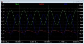
I attach a simulation of the Driscoll oscillator using the Laptech 6.144 MHz AT-cut crystal. The green plot is the waveform at the oscillator output, before the squarer: around 2.4V p-p. The blue plot is the current flowing through the crystal: around 8.8mA rms. The red plot is the waveform at the base of Q1. With the component values suggested in the BOM of the TWTMC-D the power dissipated by the crystal is around 350uW. I think this is an optimal value, high drive level that means lower phase noise but below the maximum rating of 400uW. The loaded Q of the circuit is around 82%, so starting with the unloaded Q of the crystal around 780K you get a loaded Q around 640K, that's a good point to expect very low phase noise.
A sonic comparison with the Pierce type using the same crystal could be very interesting, since the Pierce is claimed to be very good at frequencies up to 20 MHz.
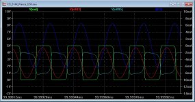
I attach the simulation of the Pierce at 5V power supply using the component values suggested in BOM of the TWTMC-P. The green plot is the output waveform after the squarer. The blue plot is the current flowing through the crystal: around 4.6mA rms. The red plot is the waveform at the input of the first inverter used as oscillator device: not more than 4V p-p, so well below the 5V of the power supply rail. The last plot (light blue) is the waveform at the input of the squarer: around 3V p-p. The power dissipated in the crystal is less than 100uW. Changing the values of some components (R1, C2, C3) one could increase the drive level, but there is the risk that the level at the input of the first inverter increases a bit, reaching a p-p voltage greater than the 5V supply rail, that's not a good practice. So I suggest to use the values indicated in the BOM.
The only superior way should be to get an SC-Cut crystal at 11.2896 MHz (Q greater than 1.1M) and then divide by 2. Or an SC-Cut at 6.144 MHz (that should reach a Q very similar to the 11.2896, that's a 3rd overtone while the 6.144 MHz is a fundamental) if we will reach the MOQ in the next batch.
The final way could be to get a 3rd overtone SC-cut crystal at 6.144 MHz, that reachs a Q greater than 2M, but it will be very expensive since we should switch from HC-43/U to HC-47/U, that's more expensive.
Attachments
Last edited:
Hello Andrea,
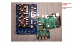
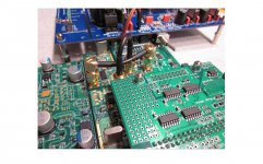
in the meantime I managed to finish my project. The aim was to play a music file that was put in the ram of a beaglebone black (BBB) by a dedicated OS (Botic) directly via i2s to the dac ("DDDac"). There is only one clock that tells the whole system what to do - yours (Clapp). There is a galvanic isolation plus clock management (Hermes / Cronus). No conversion of the signal whatsoever. The signal path is extremly short. No cables at all. The connections to your clock I also made as short as possible.
Please have a look at the attached pics.
Also refer to:
Botic:
- http://www.diyaudio.com/forums/twisted-pear/258254-support-botic-linux-driver.html
Hermes / Cronus:
- http://www.diyaudio.com/forums/twisted-pear/250583-building-open-embedded-audio-applicance.html
- http://www.diyaudio.com/forums/twisted-pear/272053-hermes-bbb-botic-cape-beaglebone-black.html
- http://www.diyaudio.com/forums/twisted-pear/272007-cronus-its-about-time.html
DDDac:
- http://www.diyaudio.com/forums/digi...-nos-192-24-dac-pcm1794-waveio-usb-input.html
The whole system works perfect! I am using a 5-way all horn system that acts like an acoustic magnifier.
Before, I managed to play music the same way using a raspberry pi (RPI). Already direct i2s-connection, but no isolation and no dedicated clock. The system used the inherent clocking of the RPI. So a huge amount of jitter. Still one could imagine the potential of the direct i2s-connection...
But now I know what good clocking means! Simply fantastic...
At the moment I can think of just three possible upgrades:
1.
better regulated power supply (for the DDDac).
2.
the DDDac uses right justified mode.There are shift registers that cause jitter (please correct me, if I'm wrong). So get rid of these and implement shifting in the OS software
3.
better clocks ;-) I've read the whole thread of the TWTMC. From what I understand and what the latest discussions are about is, that possibly the Driscoll oscillator will provide highest Q in combination with the lowest MHz-rates possible. (... so I think I might have made a "mistake" for I've chosen a 45/49 pair). So higher Q, lower phase noise = lower jitter.
Andrea! Thank You so much! Thank You for the design and again for Your "helping hand" all the way.
Kind regards,
Hans
Attachments
- Status
- Not open for further replies.
- Home
- Source & Line
- Digital Line Level
- The Well Tempered Master Clock - Building a low phase noise/jitter crystal oscillator