TWTMC All-in-One
I have received many requests to supply finished boards, but as I said several times I have just a little free time, so I cannot find the time to do the manual assembly of the boards.
The only chance is to design a standardized board with standardized parts in order to get a competitive price for external automated assembly.
If there will be enough interest, at least 100 boards, I could supply a finished board at a budget price, not much more then a pair of Crystek CCHD-957. I believe the price could be around EUR 60.
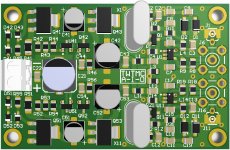
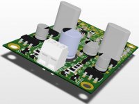
The board includes a dual Driscoll oscillator at 22/24 MHz. These are the only frequencies provided. It use a little cheaper but good enough crystals in HC-49/U package instead of HC-43/U. There are two shunt regulators on board to feed both oscillators and squarers. Output is fixed at 3V3. So one needs only unregulated or pre-regulated 10 to 12 VDC.
As soon as I will start the new GB I'll provide the final price to see if there is enough interest to launch a batch of 100 pcs.
I have received many requests to supply finished boards, but as I said several times I have just a little free time, so I cannot find the time to do the manual assembly of the boards.
The only chance is to design a standardized board with standardized parts in order to get a competitive price for external automated assembly.
If there will be enough interest, at least 100 boards, I could supply a finished board at a budget price, not much more then a pair of Crystek CCHD-957. I believe the price could be around EUR 60.
The board includes a dual Driscoll oscillator at 22/24 MHz. These are the only frequencies provided. It use a little cheaper but good enough crystals in HC-49/U package instead of HC-43/U. There are two shunt regulators on board to feed both oscillators and squarers. Output is fixed at 3V3. So one needs only unregulated or pre-regulated 10 to 12 VDC.
As soon as I will start the new GB I'll provide the final price to see if there is enough interest to launch a batch of 100 pcs.
Attachments
Hi Andrea,
... Hmmm ... thanks for the explanation Andrea. Although I have some knowledge of the terms you describe reading your description gives another & (to me) more hands-on perspective on how to practically interpret/understand some of these relationships. And I can see that the SC-cut crystals indeed have a somewhat higher Q value.
Will be interesting to see what "the proof in the pudding" eventually ends up being ...
Cheers & thanks again 😉
Jesper
Hi Jesper,
data provided are the individual measurement of each crystal made by Laptech, as I requested when I placed the order.
You can think a crystal as a series R-L-C filter with a capacitance in parallel. As you can see in the attached data, eg 6.144MHz, RR is the ESR of the crystal (R of the RLC filter), C1 is the motional capacitance (C of the RLC filter) and C0 is the capacitance of the crystal's terminals (in parrallel to the RLC filter).
Q is the Quality factor of the modelled RLC filter, and characterizes the resonator's bandwidth relative to its center frequency. The higher the Q the narrower the bandwidth, the better the crystal. Higher Q means a lower rate of energy loss relative to the stored energy of the resonator.
Typically, the higher the Q of the resonator, the lower the phase noise of the oscillator. The goal is to get highest loaded Q as possible, starting from an high Q resonator. The Driscoll and the Butler circuits provide high loaded Q, since the resonator sees a very low impedance (crystal in the emitter circuit).
... Hmmm ... thanks for the explanation Andrea. Although I have some knowledge of the terms you describe reading your description gives another & (to me) more hands-on perspective on how to practically interpret/understand some of these relationships. And I can see that the SC-cut crystals indeed have a somewhat higher Q value.
Will be interesting to see what "the proof in the pudding" eventually ends up being ...
Cheers & thanks again 😉
Jesper
@Andrea:
... just a thought ... I personally reckon that in not too long the high-end market will move to 768 kHz sampling frequency which means that the clock would need to be 45 & 49 MHz ...
And since it is relatively simple to divide a clock /2 might it be an idea to make it 45 & 49 MHz instead?
Cheers,
Jesper
The board includes a dual Driscoll oscillator at 22/24 MHz.
... just a thought ... I personally reckon that in not too long the high-end market will move to 768 kHz sampling frequency which means that the clock would need to be 45 & 49 MHz ...
And since it is relatively simple to divide a clock /2 might it be an idea to make it 45 & 49 MHz instead?
Cheers,
Jesper
@Andrea:
... just a thought ... I personally reckon that in not too long the high-end market will move to 768 kHz sampling frequency which means that the clock would need to be 45 & 49 MHz ...
And since it is relatively simple to divide a clock /2 might it be an idea to make it 45 & 49 MHz instead?
Cheers,
Jesper
Think Andrea will have MOB for all freqs. Suggest to have 317 & 78xx footprint for external ultra low noise volt reg. like ADM7150
*******************************Crystals are on the way.
Following individual measured data of AT-Cut type.
Hello Andrea.
Do you have measured data for the 5.6448 MHz AT cut crystals?
Thank you for your help.
*******************************
Hello Andrea.
Do you have measured data for the 5.6448 MHz AT cut crystals?
Thank you for your help.
Hi Alex,
5.6448 MHz crystals are from the previous batch.
You can find the individual measurement data in post #516.
@Andrea:
... just a thought ... I personally reckon that in not too long the high-end market will move to 768 kHz sampling frequency which means that the clock would need to be 45 & 49 MHz ...
And since it is relatively simple to divide a clock /2 might it be an idea to make it 45 & 49 MHz instead?
Cheers,
Jesper
Actually HDMI 2.0 is supposed to support 1.536 MHz sampling now. I think it is not useful since the files are enormous and have a very low information density. Still if that stuff interests you and you have a driving need to fill large disk drives I would recommend using a doubler (or two) to get to the target clock rate. This Mini-Circuits costs a staggering $6. Typically you will get less close in phase noise from the lower frequency multiplied.
@1audio:
Hmmm... well, yes, it actually interests me, although I know there are many different opinions and approaches to the significance of sample rates.
To this end I would also have liked to see which mini-circuits device you linked to but the link goes to a page with what looks like thousands of mini-circuit devices (they have many!) - any chance you can give a link to a specific circuit you had in mind?
Cheers,
Jesper
Still if that stuff interests you and you have a driving need to fill large disk drives I would recommend using a doubler (or two) to get to the target clock rate. This Mini-Circuits costs a staggering $6.
Hmmm... well, yes, it actually interests me, although I know there are many different opinions and approaches to the significance of sample rates.
To this end I would also have liked to see which mini-circuits device you linked to but the link goes to a page with what looks like thousands of mini-circuit devices (they have many!) - any chance you can give a link to a specific circuit you had in mind?
If I understand you correctly then starting e.g. with a 6.144 MHz crystal and then multiplying it e.g. 4 times with a suitable "device" will give less close in phase noise than a 24.576 MHz oscillator on its own? If so - very interesting! Yet, since I don't see it around much I suppose there are also side-effects to doing it in this way ... ?Typically you will get less close in phase noise from the lower frequency multiplied.
Cheers,
Jesper
Sorry about the broken link. The Minicircuit site can be troublesome. Here is where you start: Frequency Multipliers - Mini Circuits I just went surface mount and X2 but there are lots of options. I believe there are lower noise solutions but for big bucks and may not make a difference.
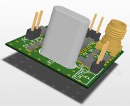
**********************************While waiting for crystals delivery, here attached some pictures of the finished boards.
DIL adapter, fundamental and overtone oscillators, daughter board and final assembly.
Thanks Andrea, I found the data I needed.
By the way....I saw that you are using 74HCU04 in your later designs, as opposed to 74HC04, used by Herbert.
I think that is a very good modification.
Good thing to see that you pay attention to the comments posted here on the forum.
With that in mind, I would like to add that I have recently found out how much work Herbert has done in oscillator design.
Most of his work is in Dutch, and not easily available.
He has done immense, detailed, lengthy work on oscillators, and I am willing to take everything he has to say very seriously.
Certainly, the simple TWTMC-C has astonishing performance. It will be difficult to do much better in terms of close-in SSB PN than RutgerS oscillator.
However, I believe (due to my own past experiences) that the TWTMC-C will sound even better in a system when 74HC04 is replaced.
You might get worse isolation, but that might not be an important objective in this context.
I would also like to remind you that vibration seems to have a VERY detrimental effect on close-in PN. There are many good articles on the net.
I believe the next step (after buliding the oscillators) would be acoustic and vibrational dampening and magnetic screening.
Thank you Herbert for your efforts. Cheers.
________________________________________
Keep up the good work, Gentlemen.
Last edited:
90/98 MHz update
After several test I have to recognize that the Colpitts-Clapp oscillator won't work with 90/98 MHz AT-Cut 5th overtone crystals.
I have tried other jfets with much more transconductance than the J310, but they aren't able to overcome the losses due to the high ESR of the crystals.
Furthermore the drive level of crystals with ESR around 40 ohm becomes too high.
The only way to get the oscillator working with the above crystals is a different circuit such as the Driscoll.
So, the members who got AT 90/98 MHz crystals to use with Colpitts-Clapp oscillator should build the TWTMC-D Driscoll oscillator, available in the next GB.
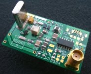
This is the finished Driscoll oscillator at 98.304 MHz.
After several test I have to recognize that the Colpitts-Clapp oscillator won't work with 90/98 MHz AT-Cut 5th overtone crystals.
I have tried other jfets with much more transconductance than the J310, but they aren't able to overcome the losses due to the high ESR of the crystals.
Furthermore the drive level of crystals with ESR around 40 ohm becomes too high.
The only way to get the oscillator working with the above crystals is a different circuit such as the Driscoll.
So, the members who got AT 90/98 MHz crystals to use with Colpitts-Clapp oscillator should build the TWTMC-D Driscoll oscillator, available in the next GB.
This is the finished Driscoll oscillator at 98.304 MHz.
Attachments
Schematics, PCBs, BOMs and Assembly guide
Attached the assembly guides of all the boards available. They contain the schematic of each board, the BOM to source the parts and the instructions to build each circuit.
- TWTMC-C: Colpitts-Clapp oscillator revised
- TWTMC-D: Driscoll oscillator
- TWTMC-D&D: daughter board (power supply, dividers, and so on) revised to supply the Driscoll oscillator and the oven board
- TWTMC-OVN: oven board for SC-Cut crystals Driscoll oscillator
- TWTMC-DIL: DIL adapter for Ian's Fifo board
Attachments
New GB will start soon
To keep the discussion exclusively technical on this thread I will start soon a separate thread for the new GB.
To keep the discussion exclusively technical on this thread I will start soon a separate thread for the new GB.
After several test I have to recognize that the Colpitts-Clapp oscillator won't work with 90/98 MHz AT-Cut 5th overtone crystals.
I have tried other jfets with much more transconductance than the J310, but they aren't able to overcome the losses due to the high ESR of the crystals.
Furthermore the drive level of crystals with ESR around 40 ohm becomes too high.
The only way to get the oscillator working with the above crystals is a different circuit such as the Driscoll.
So, the members who got AT 90/98 MHz crystals to use with Colpitts-Clapp oscillator should build the TWTMC-D Driscoll oscillator, available in the next GB.
This is the finished Driscoll oscillator at 98.304 MHz.
**********************************************
Hi Andrea.
Don't be discouraged. Clapps oscillators are frequently used in SHF range, usually several GHz...
Try bipolar transistors, like some good old BF-types.
Wonderfull work btw, bravo.
Good luck.
Last edited:
New GB
The new GB has been started at
http://www.diyaudio.com/forums/digital-line-level/291925-well-tempered-master-clock-group-buy.html
The new GB has been started at
http://www.diyaudio.com/forums/digital-line-level/291925-well-tempered-master-clock-group-buy.html
Hi,
I just asked Genesys to synthesize a Colpitts; it proposes a range only from 4-20 MHz.
For a typical xtal at 50 MHz, C1=220p, C2=22p with a 2N4416 Fet. For medium frequencies,
the caps are more or less equal.
Down at 6 MHz, C1=22p, C2=220p, just the other way around.
At 60 MHz, C1 becomes -180pF, that won't work.
Playing with the program costs me bonus points with a customer, I don't want
to stress that.
Author of Genesys is Randall Rhea; he sold it to Agilent.
Good book: Randall W. Rhea: Discrete Oscillator Design...
< https://www.amazon.de/Discrete-Osci...id=1464222904&sr=8-5&keywords=Randall+W.+Rhea >
I see, you can spend 3 times as much when you buy it used rather than new.
(and you can view a few pages on Amazon)
regards, Gerhard
Last edited:
Coming soon...
Next step: the picogate Pierce oscillator TWTMC-P....
... after vacation.
Next Saturday I'll leave for vacation, I will be in the South-west of the USA for 3 weeks. So, I have limited access to the internet to follow the thread and eventually post replies.
Next step: the picogate Pierce oscillator TWTMC-P....
... after vacation.
Next Saturday I'll leave for vacation, I will be in the South-west of the USA for 3 weeks. So, I have limited access to the internet to follow the thread and eventually post replies.
Attachments

@Andrea ... Wow, looks like a tremendous & comprehensive work ... Thanks again & may your vacation be as you best would like it to be ;-)
@1audio: Thanks, Demian. I'll look into it ... Still am a bit puzzled by the notion that a low(er) frequency base oscillator and a multiplier would be better than a pure oscillator itself at higher frequencies. I think I'll contact minicircuits to hear which of their multipliers have the lowest close-in PN (and what it may be).
Have a good day 🙂
Jesper
- Status
- Not open for further replies.
- Home
- Source & Line
- Digital Line Level
- The Well Tempered Master Clock - Building a low phase noise/jitter crystal oscillator