I was checking the guide for an online cnc service. You provide a vector image (with all cut offsets included) and they send back the finished job.
However they state that the cutting bit is 8mm dia, so the smallest hole possible is 8mm, and the thinnest elements they accept in a design are 12.5mm
Its not a big deal to redesign with 12.5mm walls, but 8mm guide holes seem excessive.
Is this a standard bit size for cnc or will other people use thinner bits? Id also prefer somebody else to work out all the cut offsets etc. Unless it really is as simple as just doing a 4mm offset outside every line.
The tool diameter will likely be predicated by a combination of material density, feed rate and machine time (usually the determining factor in cost.) Generally, you would supply a DXF/DWG file and their software would take care of the offsets - But check first. I used to do my drawings including the offsets (easy to do using the Offset function in the CAD program I used - Rhino3D). I did this so that I could see if two or more offsets clashed.
. 18:1 ratio slot port is a Bad Idea. Are you certain a properly divided slot counts as one slot? Definitely seek confirmation of this, but if it does turn out to be the case the simple fix while retaining the aesthetic would be to eliminate the centre port - you could maybe fit a badge into the recess where the middle port would have been if you were feeling vain...or a power button and an LED and make it active! That'd be sweet.
Well given the circumference to area ratio is the problem (increased drag at boundaries) then taking a long thin slot and dividing it in three cannot possibly improve things, the surface in contact with the air is higher. This is why the ratio must effectively be 18:1 or higher.. Be great if i could just add loads of bracing rings until i had 16 small square ports, but its impossible that this would improve things despite each port having a 1:1 proportion. Likewise, blanking one port would improve the ratio to 12 :1 or thereabouts, but would increase port velocity..
The vent is fine as it is. If anything he can increase the height 2-5mm and decrease the width. Granted that will increase the size a bit, but there will be wider “braces”.
dave
dave
Im now reading about port resonances. And that long ports can exhibit unwanted resonances close to the operating range. Is this already simulated in winisd or should i be concerned about this too? If there's an audible resonance above crossover frequency, how do you deal with it? Eq wouldnt help there. I read about adjusting port length and drilling holes in centre of port?
I also read that curved ports help.. So thats good for me.. Right? Agh so many questions.
I also read that curved ports help.. So thats good for me.. Right? Agh so many questions.
Curved vents will act as a low pass, keeping some HF out of the vent. The vent can act as a 1/4 wavelength resonator, this kind of topology is used to get extra bass in the Daline form of a TL. I expect the small cross-section will inhibit this thou. How long is the vent?
dave
dave
am i right in calculating the 1/4 wave resonance would be at 70.25 hz?
that sounds bad.. no? if this isnt considered by winisd, im surprised...
that sounds bad.. no? if this isnt considered by winisd, im surprised...
70 Hz fundemental + odd order harmonics.
dave
and.. is that a problem? ive no idea.. just assuming a slim port will reduce the effect doesnt sound very sure.
Its all theory. You won’t know till you actually build them. I don’t think it should be an issue, and if it is a slightly lower XO frequency can go a ways to solving the issue (assumming you goal is a hand over to the sats at 80-100 Hz.
dave
dave
hm. well ill only get one freebie job on my mates cnc machine. beyond that ill be paying. my idea is to get everything nailed down as well as i can before building.
even if i knock something up with plywood to test the port aspect out, it wont feature the bends which may or may not reduce any resonance problems.
testing a version with a larger enclosure and port under 80cm (100hz 1/4 wavelength resonance)
even if i knock something up with plywood to test the port aspect out, it wont feature the bends which may or may not reduce any resonance problems.
testing a version with a larger enclosure and port under 80cm (100hz 1/4 wavelength resonance)
ok now im really confused. been reading a bit more and discovered that winisd calculates the 1st port resonance of your design. i says mine (with the 1.21m port) should be at 142.08 hz.
is that not the same thing as the 1/4 wavelength pipe resonance we are discussing?
why is it not at 70hz then?
and actually why can i not see its effect on the spl / transfer function graph?
if its really at 142 hz then im not concerned as i will be crossing over way below that.
is that not the same thing as the 1/4 wavelength pipe resonance we are discussing?
why is it not at 70hz then?
and actually why can i not see its effect on the spl / transfer function graph?
if its really at 142 hz then im not concerned as i will be crossing over way below that.
Originally Posted by robinlawrie
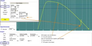
Is this already simulated in winisd
YES See my screenies 😉
If you havn't already, you should update the program http://www.linearteam.org/download/winisd-07x.exe
Attachments
YES See my screenies 😉
If you havn't already, you should update the program http://www.linearteam.org/download/winisd-07x.exe
owww. i only downloaded winisd a week or two ago, this version is very new?
and what the heck is that "use transmission line model for port simulation" tickbox? it changes my box response completely.
Originally Posted by robinlawrie
owww. i only downloaded winisd a week or two ago, this version is very new?
It's the latest version, yours is a LOT older !
and what the heck is that "use transmission line model for port simulation" tickbox? it changes my box response completely.
If you look Closely, i've merged 2 screenies that show the effect of Port Resonances, which you asked about 😉
with that checkbox ticked, my f6 and f10 values are much higher up, and i get a much nicer response with a 35 hz box tuning frequency.
is this "transmission line model" to be trusted more than the old vent model?
is this "transmission line model" to be trusted more than the old vent model?
ok so using this new winisd, which i managed to miss completely, seems a reasonable design is a 20 litre enclosure with a port tuned to 40hz.
this port is only 47 cm long and its first resonance is 365hz. port velocity is 16.5m/s
f3 is at 35hz, f6 is at 25hz and f10 at 21 hz.
with highpass filter at 20 hz, and 230 watts input, it can do 100+db output down to 25 hz without over excursion.
group delay is still a bit ugly due to highpass filter.
really does give a massively different result this new version eh? worryingly , since people have sworn by the old one for so long.
- Status
- Not open for further replies.
- Home
- Loudspeakers
- Subwoofers
- the "swissroll" compact 8" subwoofer