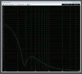
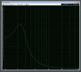
ha.. the xmax graph without the filter goes through the roof under 25 hz. with 250 watts it arrives at 40+mm excursion
to keep it within xmax i can only feed 25 watts to the driver.
anyway as noted in my edit to the previous post. i think a small adjustment to the filter and recognising the purpose of my design (its never gonna run at full whack i think) it should be ok.
to keep it within xmax i can only feed 25 watts to the driver.
anyway as noted in my edit to the previous post. i think a small adjustment to the filter and recognising the purpose of my design (its never gonna run at full whack i think) it should be ok.
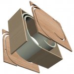
ha.. well i tried a quick approximate mockup of a rounded cube (only rounded in vertical sides) with the same internal volume and port length.. i guess it is smaller overall, but it look bigger.... which is good cos i wanted to stick with the cylindrical one.
should i be considering this in my sub design? its relatively trivial to do a rounded rectangular form instead of cylindrical.. not quite so elegant, and a bit of a PITA to model in 3d keeping all the desired proportions.. also possibly might look more bulky, and the vent path wouldnt be so smooth...
As a woofer the enclosure is usually small compared to the wavelengths produced so it matters little what shape it is.
dave

tops off.
ive not tried modelling with a thicker wall on the inner surfaces.. it would require either shrinking the internal volume ( making vent shorter, would not complete a full rotation of the box -structural weakness)
or moving the vent outwards to retain the internal volume, which would make the vent longer, requiring a narrower vent.
or do either of those and change the height of the box to compensate, although then i have to change vent height and im limited by material thickness.
-which i have not decided on, depends what is available.
neither of them a deal breaker obviously, but do you not think the 1cm thick *double layer* walls with 2cm x 6cm bracing rings every 10 cm would be quite rigid? i cant imagine a 1cm thickness flexing much over 10cm..?
id obviously choose the densest plywood i could afford..
Attachments

What driver are you using?
I like the circular one.
dave
its in the first post.. the dayton reference HO 8"
it models very well in a small vented enclosure..
I think they're both great. The rectangular one has more character, imo. It looks like an Apple product. Really excellent design.
I think maybe what does it with the rectangular shape (for me at least), is that with the cylinder, the straight lines of the port bracing aren't offset by the rest of the enclosure shape, so they look more isolated, while with the rectangle they look more integrated.
It might be interesting as an experiment, with the cylindrical design, to see how the end of the port would look if you gave it a 'circular' shape, like a sickle. I think that might technically function, albeit very marginally, as a port flare, so there's a chance that's actually the optimal shape for it.
Edit: About the thicker inner wall, probably not needed, and the design is so damned neat it almost seems a shame to spoil it with unbalanced internals even if no one ever sees them. I'd be tempted to experiment with topping it with a water-jet cut perspex viewing window that aligns directly with the cutout shape and slots into a cutout in the top layer of ply, but that's probably a bit ott.
Last edited:
...bracing rings…
As a translam those rings are not nearly as effective as braces. The double wall can be very effective (our full-on miniOnken boxes demonstrate this)
id obviously choose the densest plywood i could afford.
DEnsity is unimportant. Stiffness is. And since you are not using the ply in the direction its stiffness is most apparent strength. Extra mass without a gain in stiffness is going backwards.
dave
..the dayton reference HO 8”...
I’d actually look at using this in a 17 litre sealed box. Looks to match room gain pretty well. A sealed box is more capable of handling EQ.
Played a bit with a vented box. The same 17 litre tuned to 20 Hz looks good. But the 3 of 2x8 cm vents would need to be 2072 mm long. Reducing those to 1x7 3 off reduces vent length to 894mm althou that is below the recommended minimum vent size — i don’t see that as an issue with such high resistance vents.
dave
ive tried a sealed box,
to try to match the spl around 30-40 hz with eq or a linkwitz transform drives the excursion to the moon.
however, im obviously missing something.. you said "looks to match room gain pretty well"
could you explain what this means? i thought the flattest response to the lowest frequency was the ideal..
your two suggestions provide smoother falloff, but hit f3 at 41 and 52 hz.. mine hits f3 at 29 hz.
obviously you know something (many things?) i do not about desireable response curves!
bear in mind my room is a) not very typical and b) acoustically not-very-good
its a 5m x 8m stone walled (plastered) room with a 5.5metre high barrel vaulted cieling, and a tiled floor.
with all the furnishing in now at least it doesnt echo like a church, but intelligibility of music isnt the best. its rented and my GF is the boss, so acoustic treatments are out. i was planning a couple of small subs and some DRC to try to improve matters. hence the project..
Last edited:
as requested, the round one with the vents blended in more.. im not sure if i like it more, or less!
and yes, i did toy with a perspex lid idea at the start.. shame not to see inside.. but its a bit bling(i could also put colour change leds in the vent channels that change colour with the frequency😉 , less practical and damn expensive for thick stuff.
and yes, i did toy with a perspex lid idea at the start.. shame not to see inside.. but its a bit bling(i could also put colour change leds in the vent channels that change colour with the frequency😉 , less practical and damn expensive for thick stuff.
Attachments

Last edited:
however, im obviously missing something.. you said "looks to match room gain pretty well"
could you explain what this means? i thought the flattest response to the lowest frequency was the ideal..
Unless you are playing outside that usually yields too much bass low down. The room you put the woofer will add a gain below a certain frequency that a sealed woofer is more complentary to. You ideally want a slow roll-off that starts in the same place your room gain kicks in (room dependent).
your two suggestions provide smoother falloff, but hit f3 at 41 and 52 hz.. mine hits f3 at 29 hz.
Forhget F3 it is meaningless (ref Toole). Look at F10 and F6. The 2 examples i gave are the same with the same curve, just a different choice of vents. If your sim software thinks differently i would be worried.
its a 5m x 8m stone walled (plastered) room with a 5.5metre high barrel vaulted cieling, and a tiled floor.
The unflat ceiling will be a boon to evening out the bass response, stone & plaster usually give more gain (stiffer walls). Your room is a bit smaller than mine, and stiffer. I remember when a fellow brought his 3-ways with 7” extremis up for diyFEST. The room gain with just those drivers was too much.
so acoustic treatments are out. i was planning a couple of small subs and some DRC to try to improve matters.
Multiple woofers will help smooth out the bass, but it sounds like your issues are much higher up in frequency where DRC will not be effective. Think bookshelves with books, records, furniture, carpets etc even pictures on the wall as acoustic treatments.
dave
I remember when a fellow brought his 3-ways with 7” extremis up for diyFEST.
Now that i think further there were 2/box which was the inspiration for the woofer set-up in our Ellispas
An externally hosted image should be here but it was not working when we last tested it.
dave
Here's a dude who has already dabbled in this style - big ports that curve around the box. Some are speculative (pictured), and some built (the link).
Sidewinder Subwoofer
What about bendy ply, or whatever it is in the Cornu horn?
Or even sheet metal?
Sheet metal, well damped, is pretty inert - e.g. my hot water cylinder 🙂
Good wisdoms. Also the bit about sealed + EQ. Here be a link that gives lots of practical info on room gain:
Data-Bass
Their room gain started at 190Hz, and is crazy uneven, cos that's how rooms do.
Sidewinder Subwoofer
Waste of wood is one of my main gripes with this construction method, but as your design enables a port that would otherwise be extremely difficult to achieve effectively without it, it's more justified than most.
What about bendy ply, or whatever it is in the Cornu horn?
Or even sheet metal?
Sheet metal, well damped, is pretty inert - e.g. my hot water cylinder 🙂
Unless you are playing outside that usually yields too much bass low down. The room you put the woofer will add a gain below a certain frequency that a sealed woofer is more complentary to. You ideally want a slow roll-off that starts in the same place your room gain kicks in (room dependent).
Good wisdoms. Also the bit about sealed + EQ. Here be a link that gives lots of practical info on room gain:
Data-Bass
Their room gain started at 190Hz, and is crazy uneven, cos that's how rooms do.
Attachments
The 2 examples i gave are the same with the same curve, just a different choice of vents. If your sim software thinks differently i would be worried.
dave
i was referring to your suggestions of a 17 litre sealed enclosure and a vented box tuned to 20 hz. im using winisd, and get different responses from both.. is that what you meant?
Is there any logic to the idea of seeking the flattest response possible to allow more flexibility in eq?
Its much easier on the driver to subtract power at lower frequencies that try to bump it up.. also the extra extension provided by your proposals is all under 20 hz, where i would need a highpass anyway..
bear in mind i will be using active eq in any case..
(i have the system running from an htpc, it gets used currently more for film/tv duties, although thats possibly because music doesnt sound as nice as it could)
im going to start by getting a calibrated mic and doing some corrections on the pc. if it improves things noticeably i might invest in a minidsp to provide more flexibility in sources.
ive already got big bookshelves, a giant sofa in the middle of the room, and pictures on most free wall surfaces. only zones available for any kind of treatment would be the curved cieling or the tiled floor. got some rugs down but carpeting would be a tragedy ( patterned vintage italian tiles)
sorry im resisting your certainly sage advice! .. its hard to look at a graph that provides, apparently massively less low spl as being better than my nice flat response!
ive spent weeks going through dozens of drivers to find one that can provide a flat response as low as possible. .. hurts to think ive been wasting my time!
out of interest i modelled a box version with standard construction techniques and 18mm mdf.
considering the box form is more space efficient ( for stacking maybe)
its impressive how much bigger it looks that the other two, with the cylinder appearing the smallest. if you overlay them you can see the box is smaller along its 90 degree axes than the cylinder, but the corners fill visual space much more.
Attachments

- Status
- Not open for further replies.
- Home
- Loudspeakers
- Subwoofers
- the "swissroll" compact 8" subwoofer