MikeHunt79 said:
If you don't mind me asking, what do you have in your car now?
I currently have a dual driver autotuba in mine, and while is sounds great, it is a little large as it fills my entire boot (trunk)!
I was wondering if there is something similar which is smaller yet gives the same rising response of the AT?
I was thinking maybe a TH tuned to 60Hz, maybe with a 8" MCM but maybe a 12" driver would work better?
I used to have a three hour commute everyday, and I was running Unity horns up front. In the trunk I had an autotuba clone for a while, and then I switched to a pair of eights in a severely undersized front-loaded horn.
I documented most of it over at audiogroupforum.com.
It's really hard to improve on the autotuba; I've tried half a dozen times. If you make it any smaller, the response goes to hell. To get the F3 lower, you have to make it a LOT bigger.
I still have the clone in my garage, and I'm hoping to measure both the tapped horn and the autotuba clone head-to-head.
Looking at a LP at 100Hz iFFT (IR) the difference might not be significant in the time domain. Instead of 4 spikes it is a lump just like on a TH with one speaker. Even with two 15" drives after one another. Wavelength is just too long for the IR to get smeared.
The strength of the TH is that it does not continue to resonate much beyond the initial 2-3 cycles that is takes to "fill" the TH.
Unlike ported or even closed boxes that happily continues to give output 5-10 cycles away.
I don't get the same bandwidth increase like you though.
However I do use one vs two 15" drive in a 210L vs 400L TH.
So it might only apply to smaller drives. I don't know.
Please keep testing as it is very interesting.
David_Web said:Looking at a LP at 100Hz iFFT (IR) the difference might not be significant in the time domain. Instead of 4 spikes it is a lump just like on a TH with one speaker. Even with two 15" drives after one another. Wavelength is just too long for the IR to get smeared.
The strength of the TH is that it does not continue to resonate much beyond the initial 2-3 cycles that is takes to "fill" the TH.
Unlike ported or even closed boxes that happily continues to give output 5-10 cycles away.
I don't get the same bandwidth increase like you though.
However I do use one vs two 15" drive in a 210L vs 400L TH.
So it might only apply to smaller drives. I don't know.
Please keep testing as it is very interesting.
I had mixed results as well. Here's a few things that I tried:
#1 - I started out with a cabinet that's very similar to a Danley TH-Mini. Instead of a twelve, it uses two eights. It has a dramatic flare at the mouth. In this cabinet, I saw substantial improvements in bandwidth and smoothness with two drivers, and to a lesser degree with four.
#2 - I tried modeling a tapped horn with a modest flare. In my experience, these enclosures are easy to build, but suffer from a lot of nasty resonances. With multiple woofers, there was no real improvement. In some cases it was much worse.
#3 - One idea I had was that staggering the woofers using the golden ratio (1.62) might smooth out resonances. This seems to be promising; I was able to achieve a very wide bandwidth by using four woofers which use a spacing ratio that matches the golden ratio. The only drawback is that the F3 rises quite a bit.
Just some food for thought! The use of multiple woofers seems to extend the bandwidth without hurting the efficiency.
Patrick Bateman said:
I had mixed results as well. Here's a few things that I tried:
#1 - I started out with a cabinet that's very similar to a Danley TH-Mini. Instead of a twelve, it uses two eights. It has a dramatic flare at the mouth. In this cabinet, I saw substantial improvements in bandwidth and smoothness with two drivers, and to a lesser degree with four.
#2 - I tried modeling a tapped horn with a modest flare. In my experience, these enclosures are easy to build, but suffer from a lot of nasty resonances. With multiple woofers, there was no real improvement. In some cases it was much worse.
#3 - One idea I had was that staggering the woofers using the golden ratio (1.62) might smooth out resonances. This seems to be promising; I was able to achieve a very wide bandwidth by using four woofers which use a spacing ratio that matches the golden ratio. The only drawback is that the F3 rises quite a bit.
Just some food for thought! The use of multiple woofers seems to extend the bandwidth without hurting the efficiency. It does seem to require a different kind of driver though. The high FS / moderately high QTS drivers that work so well in tapped horns seem to suffer from a lack of bandwidth. I had better results with drivers that offered a EBP. I guess that's why they call it EBP?
Unity horns in a car, that's a new one on me! I'll take a look at audiogroupforum.com, I'm intrigued.Originally posted by Patrick Bateman
I used to have a three hour commute everyday, and I was running Unity horns up front. In the trunk I had an autotuba clone for a while, and then I switched to a pair of eights in a severely undersized front-loaded horn.
I document .d most of it over at audiogroupforum.com.
It's really hard to improve on the autotuba; I've tried half a dozen times. If you make it any smaller, the response goes to hell. To get the F3 lower, you have to make it a LOT bigger.
I still have the clone in my garage, and I'm hoping to measure both the tapped horn and the autotuba clone head-to-head.
I do have the autotuba plans and sketchup models, so it would be pretty easy to work out the dimensions so I could sim it in Hornresp, but as you said, it's hard to get the same rising response, especially with a Tapped horn.
Right now I don't mind having a massive sub in the boot, so I can keep it in there while I experiment a little with TH's.

I'd be interested to see your measurements of the clone against the TH once they're done, I keep meaning to try my dual driver autotuba outside once I get ARTA up and running...
MikeHunt79 said:
Unity horns in a car, that's a new one on me! I'll take a look at audiogroupforum.com, I'm intrigued.
I do have the autotuba plans and sketchup models, so it would be pretty easy to work out the dimensions so I could sim it in Hornresp, but as you said, it's hard to get the same rising response, especially with a Tapped horn.
Right now I don't mind having a massive sub in the boot, so I can keep it in there while I experiment a little with TH's.
I'd be interested to see your measurements of the clone against the TH once they're done, I keep meaning to try my dual driver autotuba outside once I get ARTA up and running...
I love my home speakers (Gedlee Summas) but the Unities can do one thing that the Summas can't. The unities sound amazing even if you're seated within a few feet of the waveguide, while the Summas really need a bit of distance to "integrate" fully. I believe this is because there's a fifteen inch gap between the woofer and the tweeter in the Summa, and in the unity the gap is just three inches.
So what does this have to do with a car?
Well, in a car you're seated way too close to the speakers. So the tight integration of the midrange and the tweeter has a lot of benefits in a car.
I see a lot of guys trying to cram eight inch woofers into the front stage of their cars, and it's a dumb idea. It's impossible to integrate, because you're so close to the woofers.
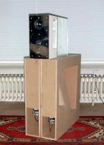
The glue has barely dried on the 12" tapped horn, but I wanted to measure it real quick. Here's a pic:
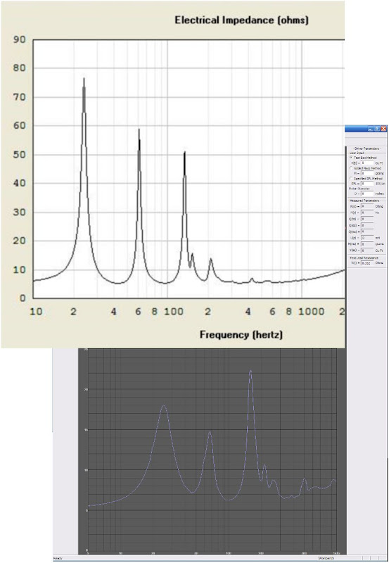
The good news is that we see two deep impedance troughs, which indicate that this is behaving like a tapped horn should. The bad news is that they're about 15% too high.
I took these measurements with the tapped horn up against a wall, and also in the middle of the floor of my listening room. Didn't seem to make a difference in the impedance plot.
At first I was worried that my hypothesis that the mouth extends into the room was incorrect. I think the jury is still out though. I messed around with the parameters in Akabak a bit, and the mismatch between the measured results and the simulated results appears to have more to do with the length of the line inside of the horn, not outside.
I'm going to go hook it up in the car, and I'll probably do some electrical and acoustical measurements of that setup in the next week or two.
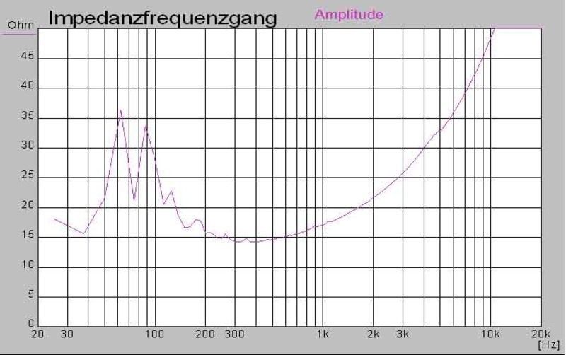
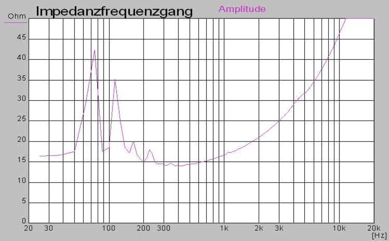
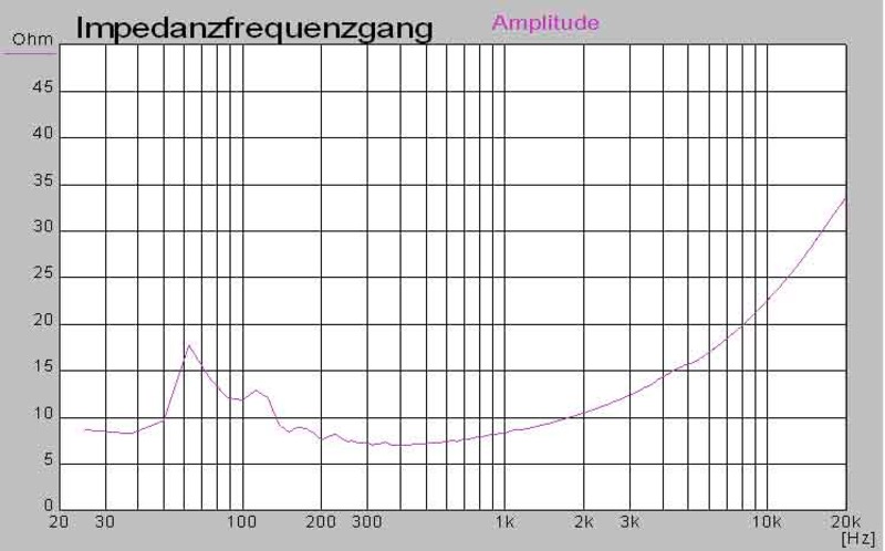
imp reduce
Hello,
if you take two different horns you can reduce the IMP
look my Subfanfare,
if you take 4 (2+2) you can reduce it more
and you get 4 Ohm
here single imp of the long and short horn and the sum
driver WAL 416 Mivoc.
you get a cleaner bass with better contour,
enclosure movement is smaller because no big pressure changes,
and the AMP likes it much more, here below 50 Hz no IMP peak
but down to 35 Hz.


Attachments
Posted some subjective observations here:
http://www.diymobileaudio.com/forum...73-tapped-horn-car-diyma-12-a.html#post744111
In a nutshell, this thing plays really loud. Definitely a huge improvement over the sonotube tapped horn that I described in my "tapped horn for dummies" thread.
It also has huge bandwidth; it's playing up to 2khz easy, maybe higher. (haven't done any acoustice measurements... yet.)
Patrick - thank you for sharing your results.
It will be fun to compare your TH reults to jbell's FLH. Both of you are using 2 - 8" MCM in horn loaded subs. As a "horn-rookie", I can't think of a better way to learn about horn loaded subs for around $100!
Thanks again,
Steve
It will be fun to compare your TH reults to jbell's FLH. Both of you are using 2 - 8" MCM in horn loaded subs. As a "horn-rookie", I can't think of a better way to learn about horn loaded subs for around $100!
Thanks again,
Steve
CrazyTubax86 said:Let us know as soon as you get some measurements. In car and in the open.
Now that it's been in the car for a week, some observations:
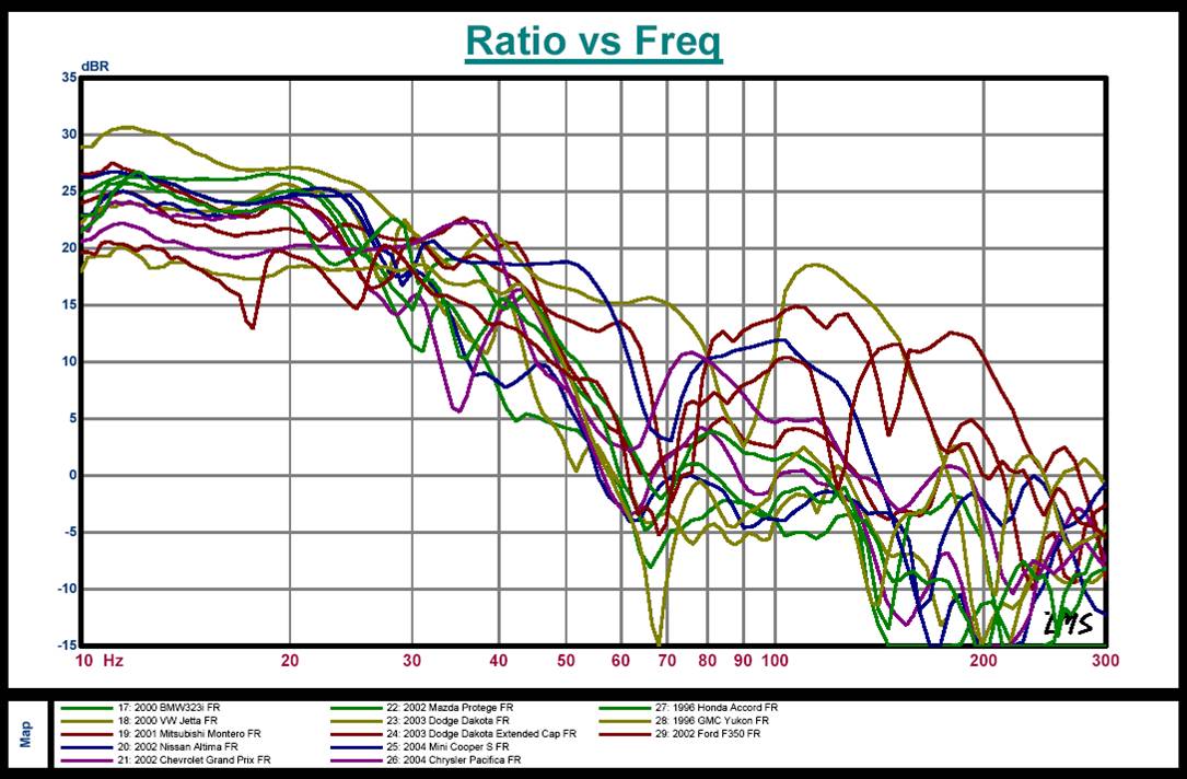
#1 - There's some kind of weird resonance going on. I'm 99% certain this is cabin gain rearing it's ugly head, because it sounds a lot more "natural" in the house. According to Andy Wehmeyer's graphs, I should expect a bump of about 8db at 50hz. Of course, this is difficult to predict because that assumption is based on three things:
a: That Andy's graphs of a '96 Accord hold true for a '05 Accord
b: That the simulations of the TH are perfect
c: That cabin gain is consistent throughout the car (we know that's false.)
The bottom line is that I need to get my mic and an EQ in the car.
After doing car subs for over a decade, I sincerely believe that bandpass and other exotic subs get a bad rep in the car world because it's really easy to wind up with too MUCH bass. IE, it's easy to create narrow resonances which sound boomy in a car with an exotic sub. So it's not the sub or the design that's at fault, it's the hostile environment of the car itself.
When I was a teenager I used to hang out at Speakercraft in Riverside all the time, and I once told one of the techies there that I was building a bandpass subwoofer. His reply was "don't build one of those, bandpass subs are for guys that want to make their rap music sound boomier." 😀
#2 - This thing can handle waaaaay more power than the simulations show. According to the sims I should be bottoming out the woofer with a hundred watts, but it's not showing any strain at all. These tapped horns can eat a lot of watts. I'm guessing that cabin gain is increasing our excursion limits too, which is a safe bet.
Here's Andy's graphs:
"if you take two different horns you can reduce the "
Your dual length horns are not practical for high output situations like car audio or PA unless two amplifiers are used so you can cut-off the low end below the 1/4W point to limit cone motion.
Your dual length horns are not practical for high output situations like car audio or PA unless two amplifiers are used so you can cut-off the low end below the 1/4W point to limit cone motion.
Hello djk,
" "if you take two different horns you can reduce the "
Your dual length horns are not practical for high output situations like car audio or PA unless two amplifiers are used so you can cut-off the low end below the 1/4W point to limit cone motion."
No, look the measurements of my double horns,
this technic is for every application useful,
please read "about what" in the middle
http://www.hm-moreart.de/11.htm
djk said:"if you take two different horns you can reduce the "
Your dual length horns are not practical for high output situations like car audio or PA unless two amplifiers are used so you can cut-off the low end below the 1/4W point to limit cone motion.
I've built a simple Akabak model for Horst's dual tapped horns and started playing with possible ways to cause the horns to interact (for example, common mouth) so that the "longer" horn will control the excursion of the "shorter" horn below its resonance. This would allow a single amplifier and high-pass filter. I'm not too hopeful though, Horst has been designing (and, more importantly, building) horns for much longer than I have.
OK, I've done some preliminary checks.
Take two tapped horns with identical drivers and 5/7 length ratios (for example, 2.5 and 3.5 metres). Give them a common last segment (S3) that has a throat area equal to the combined mouth areas of the second segments of the two horns. (Conceptually, imagine two tapped horns placed side by side, with the common walls cut back to just before the drivers.)
Now progressively reduce the mouth area of the combined horn while watching the excursions of the two drivers. The excursion of the driver in the higher frequency horn will be progressively reduced at frequencies down to the resonant frequency of the lower frequency horn. There's no free lunch - efficiency drops slightly, and the excursion of the longer horn driver increases somewhat over what it was as a separate horn. The main advantage of such a combination is that the drivers can be powered from a single amplifier with a single high-pass filter for excursion control.
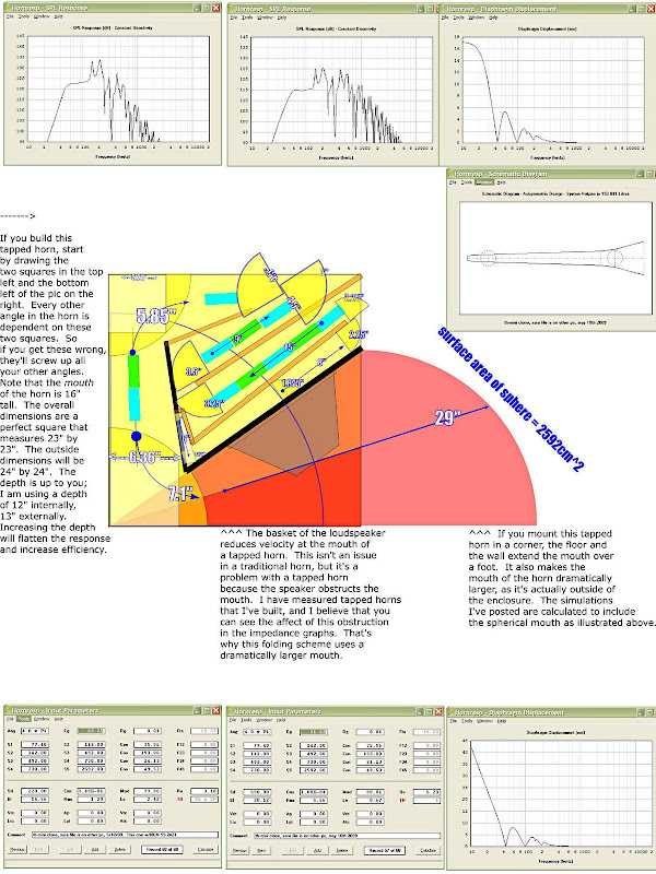
Here's some measurements of the tapped horn with a P-Audio SN12MB.
These are from my car, so keep in mind there's going to be resonances and cabin gain going on here.
First, lets look at the sims:
(response is at the top, in the middle.)
Here's the smoothed response, taken at the driver's seat:
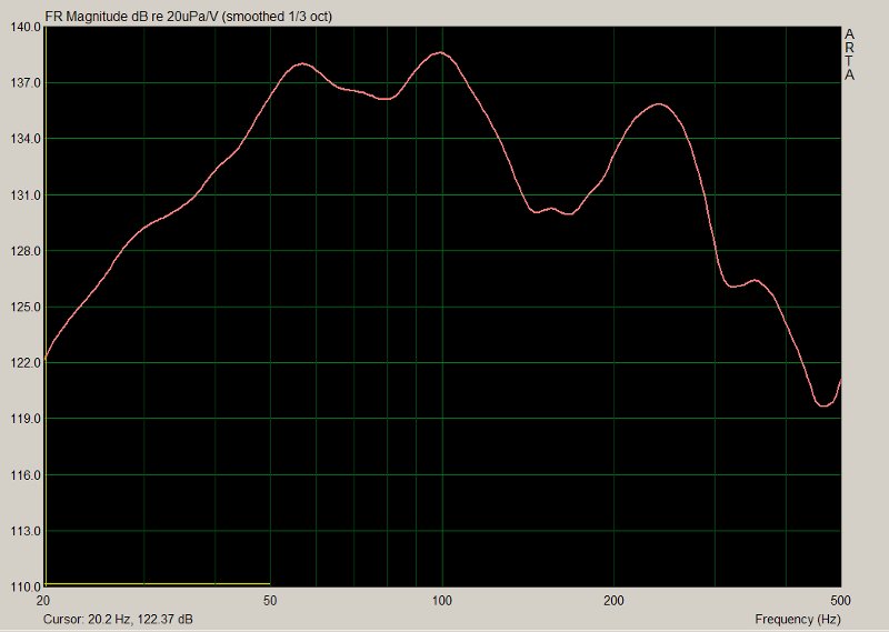
Here's my favorite graph. It has the response at the driver's seat, and at the passengers seat. So you can get an idea of what resonances are due to the cabin, and which are due to the sub.
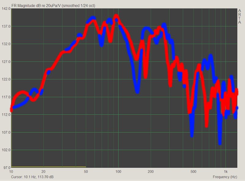
If we compare the two graphs, we're getting about 12db of gain at 25hz. This is actually a bit low; sealed subs in car often pick up 15-20db at 25hz.
I'm guessing that the horn doesn't behave like a sealed box in a car, since there's quite a bit of gain "inherent" in the tapped horn itself.
It's still very light, very small, and gets VERY loud.
This project turned out pretty well.
These are from my car, so keep in mind there's going to be resonances and cabin gain going on here.
First, lets look at the sims:
(response is at the top, in the middle.)
Here's the smoothed response, taken at the driver's seat:
Here's my favorite graph. It has the response at the driver's seat, and at the passengers seat. So you can get an idea of what resonances are due to the cabin, and which are due to the sub.
If we compare the two graphs, we're getting about 12db of gain at 25hz. This is actually a bit low; sealed subs in car often pick up 15-20db at 25hz.
I'm guessing that the horn doesn't behave like a sealed box in a car, since there's quite a bit of gain "inherent" in the tapped horn itself.
It's still very light, very small, and gets VERY loud.
This project turned out pretty well.
Patrick,
Looks like some serious level!
I'm wondering why the differing response from drivers to passenger seat,
where is the horn placed in your car?
Do you know how many volts (or watts) you applied in the test?
What was the test signal?
Have you tested it outside?
Did you check the actual cone excursion?
Looks like some serious level!
I'm wondering why the differing response from drivers to passenger seat,
where is the horn placed in your car?
Do you know how many volts (or watts) you applied in the test?
What was the test signal?
Have you tested it outside?
Did you check the actual cone excursion?
I should have mentioned - I was looking for maximum clean signal, so the SPL levels are not calibrated. I'd guess it was around 100DB, but it's not calibrated...
The passenger plot and the driver plot are useful because they reveal whether a dip is due to where the mic is located, or the enclosure, or potentially the actual width and length of the car.
In other words, the sound in a car can change if you move your head even a few inches. That's why you need to measure the response in a few locations, and look for the average.
The obvious solution to this problem is to use a brief gated measurement, but that's not practical at low frequencies. While these measurements ARE gated, the gate is quite long, to get accurate results at low frequencies.
One alternative would be to stick the mic right into the horn, so the horn sound swamps the reflections, but I actually WANT the reflections in the measurement, since that's how it will be listened to.
I'd measure it outside but it's raining right now 🙁
Microphones don't like rain 🙁
- Home
- Loudspeakers
- Subwoofers
- The Smallest Tapped Horn