Patrick Bateman said:
I'd really love to find a woofer that can handle a couple of thousand watts and works in a horn.
Ok, your not understanding the concept of a horn. A couple of thousand watts in a horn would give you permanant hearing loss from one hundred feet, outside!! The Tapped horn we built with a 12" JBL didn't model out anywhere near as well as the Tang Band and turning it up to full volume with a 30 Watt amplifier would be too painful to even consider. The very small box I modeled above will play bass at volumes you never even imagined from a sealed or ported box.
120db is the threashhold of pain. If you played this sub at full volume inside a car you would do permanant damage to your ears. So unless your building a system for a very large stadium "a couple thousand Watts" is completely ridiculous and unnecessary.
Patrick Bateman said:
I have eight subs in my home theater, but they can't compare to the "impact" you get with a big sub in a car. It's just a whole different experience.
Imact is what tapped horns excell at. Beyond discription.
Patrick Bateman said:I wasn't "blown away" by the first tapped horn that I built. While it plays very VERY low, it doesn't offer the huge efficiency I'd hoped for. It led to an interesting debate of the design's merits here:
tapped horns vs bandpass boxes
Here's a pic of the tapped horn in question:
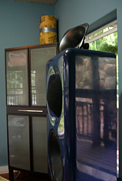
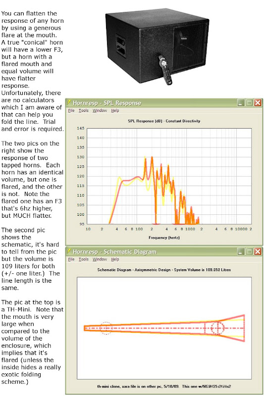
I ran some tests on it, and found that it's not behaving like the model would predict. I did some thinking about this, and I think it's because the mouth is so small. In a 'normal' horn you can get away with this to some extent, but in a tapped horn you have the woofer itself sitting in the mouth, so it's a good idea to use a dramatic flare at the mouth.
Does that make sense? Tapped horns can still be made very VERY small, but you need to compensate for that big hunk of steel and iron that's taking up bunch of space at the mouth.
I've designed a new box that incorporates a humongous mouth. In addition, it's explicitly designed for corner loading. In fact the computer simulation assumes that the mouth extends over a foot into the room.
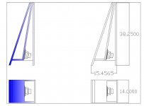
Here's a thumbnail of the design:
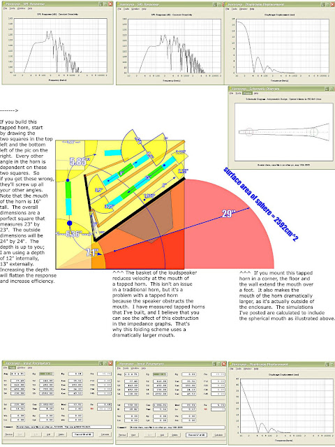
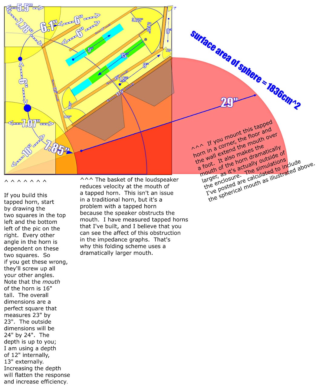
download blueprint here
All the dimensions are in the pic. The simulations were performed with the exact same box, and two different woofers. The first is a P-Audio SN-12MB which costs about $150 from Loudspeakers Plus. The second simulation is a quad of MCM 55-2421s. You can get four of them for about $120 from MCM. The MCM offers a lot more output, but the box will be a lot heavier too. The B&C 12" that's used in the TH-Mini will probably work too. Out of respect for Tom's business, I didn't offer any plans for that.
I really wasn't trying to clone the TH-Mini with this design, even though it looks *very* similar. I was just trying to improve on the design that I offered here a year ago. I've noticed that there's a lot of tapped horn designs floating around that look cool on paper, but won't actually work in the real world. It's fun to play with horn response, the tricky part is actually folding the horn and cramming it into a box. I intentionally chose dimensions that are pleasing, as the tapped horn I'm using now is ugly as sin. I'm hoping this one won't look as ridiculous as the last one!
The MCM 55-2421 works really well in horn enclosures. The design that I posted yesterday was designed primarily for the P-Audio SN-12MB. I went that route because the woofer is very lightweight, and this will probably go in a car.
Yesterday I mentioned that a quad of MCM woofers work nicely in the box.
Here's a new design, which only uses a pair.
This box has a few advantages:
#1 - It's 25% smaller than the box from yesterday.
#2 - It's cheaper to build; the MCM woofers are only $35 each.
#3 - It can take more power, as the MCM woofer has more excursion than the P-Audio.
#4 - The woofers are easier to find, as they're virtually identical to a Tangband W8. (The TB is more expensive, better built, and has more excursion.)
#5 - Because the MCM woofers are wired in parallel, they're more efficient if you have an amp that's 2ohm stable.
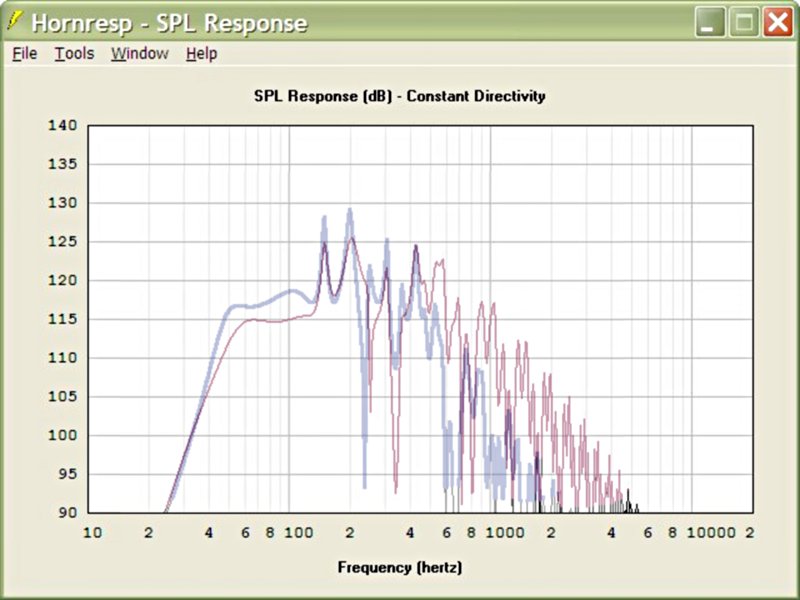
Without further ado, here are the pics. The first pic compares the efficiency of both designs. From 40hz to 100hz, the MCM is about 4db more efficient, mostly due to the 2ohm load.
The second pic is the box diagram. It has a shorter pathlength. The external dimensions are 24" x 24" x 9.5". That's a hair over three cubic feet.
There is always a compimise between ultimate efficiency(dynamics) and bass extention. It's usually better to lean toward dynamics. A Tapped horn built properly should out do anything when it comes to dynamics. My guess is the first one you heard was comprimised too much in the name of extention and so lost the slam. My design for the TB may be also, I'll have to see. It has more power handeling and excursion than anyone will ever use in their livingroom from what I can see. If you consider how many drivers your using and the time and wood used my design ends up being cheaper too. 120db literaly hurts! So if you hit that your golden!
Patrick Bateman said:
You're putting too much in the URL. If you drop the last part(stop after s1280) it works great.
boydon_lepasci said:
You're putting too much in the URL. If you drop the last part(stop after s1280) it works great.
Thanks for the tip! Google doesn't publish a way to link to images that are over 800 pixels wide, so I just guessed on the URL, and it worked! Didn't realize that stripping the last part makes it work better. I have a hunch that Google does this so you don't embed humongous images on web forums 😀
Odd - the link I posted works for me when I test it.
GM - your link does not work for me in Firefox, but does work in Internet Explorer.
Sorry for the confusion.
GM - your link does not work for me in Firefox, but does work in Internet Explorer.
Sorry for the confusion.
Interesting! I wonder why, especially since I'm running Mozilla Firefox also. Yours I get an error message and of course my link works for me in Firefox, but both mine and yours works in IE. This really makes no sense to me.
GM
GM
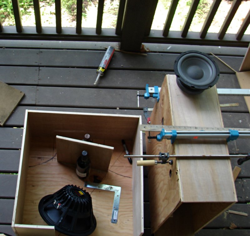
Here's some pics of the boxes. I noticed in the diagram I forgot to include the height of the mouth! It's sixteen inches tall. The first box is 13.5" wide, the second is 9.5" wide.
The simulation for the P-Audio is based on a width of 12", but then I noticed the frame is 12.25". Shouldn't make a big difference in the response...
The simulation for the P-Audio is based on a width of 12", but then I noticed the frame is 12.25". Shouldn't make a big difference in the response...
Based on a discussion here, I threw together a pic of what this box would sound like if I didn't use a flare at the mouth.
The idea is that using a significant flare at the mouth flattens the response, while raising the F3. Since this box will likely end up in a car, a low F3 is actually a bad thing (due to cabin gain.)
Flatter response and a small box are definitely what we're after here.
The idea is that using a significant flare at the mouth flattens the response, while raising the F3. Since this box will likely end up in a car, a low F3 is actually a bad thing (due to cabin gain.)
Flatter response and a small box are definitely what we're after here.
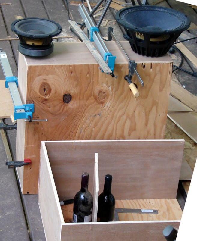
So I'm building two boxes. One for a single twelve, and one for dual eights. Just to cover my bases, I created an Akabak script to model a tapped horn with dual woofers. (Horn response models them as if they're radiating from the same point in space; it doesn't account for the gap between them.)
I was a bit surprised to see that the efficiency nearly doubles, and 3rd harmonic distortion is reduced too!
Talk about a free lunch 🙂 🙂 🙂
Here's a pic of the response; note it's more efficient from 60-150hz, and *less* efficient from 250hz on up (where the distortion is.)
Niiiiiice....
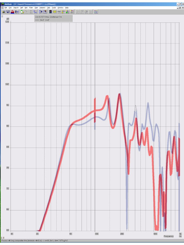
The graph looks a little weird because I use a photo editor to merge the two simulations (I don't think there's a way to compare two designs in Akabak or Hornresp.)
I was a bit surprised to see that the efficiency nearly doubles, and 3rd harmonic distortion is reduced too!
Talk about a free lunch 🙂 🙂 🙂
Here's a pic of the response; note it's more efficient from 60-150hz, and *less* efficient from 250hz on up (where the distortion is.)
Niiiiiice....
The graph looks a little weird because I use a photo editor to merge the two simulations (I don't think there's a way to compare two designs in Akabak or Hornresp.)
Here's an Akabak model for a tapped horn with dual woofers.
It's a bit confusing; let me know if it's hard to figure out where the taps are. I included a diagram.
System 'S1'
|DATA EXPORTED FROM HORNRESP - RESONANCES NOT MASKED
|COMMENT: th-mini clone, xara file is on other pc, 5/10/09. This one w/MCM 55-2421x2
|========================================================================================================
|REQUIRED AKABAK SETTINGS:
|File > Preferences > Physical system constants:
|Sound velocity c = 344m/s
|Medium density rho = 1.205kg/m3
|Sum > Acoustic power:
|Frequency range = 10Hz to 20kHz
|Points = 533
|Input voltage = 31.62V rms
|Integration = 2Pi-sr
|Integration steps = 1 degree ... 1 degree
|Integration method = Cross
|========================================================================================================
Def_Const |Hornresp Input Parameter Values
{
|Length, area and volume values converted to metres, square metres and cubic metres:
Rg = 0.01e-0; |Amplifier output resistance (ohms)
S1 = 54.83e-4; |Horn segment 1 throat area (sq cm)
S2 = 70.00e-4; |Horn segment 1 mouth area and horn segment 2 throat area (sq cm)
S3 = 90.00e-4; |Horn segment 2 mouth area and horn segment 3 throat area (sq cm)
S4 = 387.00e-4; |Horn segment 3 mouth area and horn segment 4 throat area (sq cm)
S5 = 604.40e-4; |Horn segment 4 mouth area and horn segment 5 throat area (sq cm)
S6 = 1401.30e-4; |Horn segment 5 mouth area and horn segment 6 throat area (sq cm)
S7 = 1836.00e-4; |Horn segment 6 mouth area (sq cm)
L12 = 25.64e-2; |Horn segment 1 axial length (cm)
L23 = 30.00e-2; |Horn segment 2 axial length (cm)
L34 = 170.00e-2; |Horn segment 3 axial length (cm)
L45 = 11.00e-2; |Horn segment 4 axial length (cm)
L56 = 40.60e-2; |Horn segment 5 axial length (cm)
L67 = 22.10e-2; |Horn segment 6 axial length (cm)
|Parameter Conversions:
Sd = 440.00e-4; |Total diaphragm area for 2 parallel drivers (sq cm)
}
|========================================================================================================
|Network node numbers for this tapped horn system:
|0-Voltage-1-Resistance-2----------
| x x
| --Driver1------ ---------------------------
| x -Driver2-------------- x
| x x x x
| 8-Segment-9-Segment-10-Segment-11-Segment-12-Segment-13-Segment-14-Radiator
|========================================================================================================
Def_Driver 'Driver'
Sd=220.00cm2
Bl=14.56Tm
Cms=3.48E-04m/N
Rms=1.20Ns/m
fs=31.0000Hz |Mmd = 73.86g not recognised by AkAbak, fs calculated and used instead
Le=2.42mH
Re=3.40ohm
ExpoLe=1
System 'System'
Resistor 'Amplifier Rg'
Node=1=2
R={Rg}
Driver Def='Driver''Driver 11'
Node=2=0=9=12
Driver Def='Driver''Driver 21'
Node=2=0=10=13
Waveguide 'Horn segment 1'
Node=8=9
STh={S1}
SMo={S2}
Len={L12}
Conical
Waveguide 'Horn segment 2'
Node=9=10
STh={S2}
SMo={S3}
Len={L23}
Conical
Waveguide 'Horn segment 3'
Node=10=11
STh={S3}
SMo={S4}
Len={L34}
Conical
Waveguide 'Horn segment 4'
Node=11=12
STh={S4}
SMo={S5}
Len={L45}
Conical
Waveguide 'Horn segment 5'
Node=12=13
STh={S5}
SMo={S6}
Len={L56}
Conical
Waveguide 'Horn segment 6'
Node=13=14
STh={S6}
SMo={S7}
Len={L67}
Conical
Radiator 'Horn mouth'
Node=14
SD={S7}
I cranked out a model for four woofers, and now the first peak is completely gone! This really widens the bandwidth in a huge way.
Hmm. You seems to have connected the drivers wrong.
The first driver needs to be first and last.
The second in the middle (as you fold around)
Unless you have some strange folding.
Driver Def='Driver''Driver 11'
Node=2=0=9=12
Driver Def='Driver''Driver 21'
Node=2=0=10=13
vs
Driver Def='Driver''Driver 11'
Node=2=0=9=13
Driver Def='Driver''Driver 21'
Node=2=0=10=12
Might be wrong though.
I can't see much benefit now.
Impulse response is smeared out due to additional peaks from drivers.
Not sure if it matters at LF though.
I will have to do further testing as I just finished my own model.
If you don't mind me asking, what do you have in your car now?Patrick Bateman said:Amplifiers are ridiculously cheap, and it would be fun to have a boomin' system in the car. I cloned an autotuba a few years back and fed it with an 800 watt amp, that was a lot of fun until I got sick of the sheer size of the box.
I currently have a dual driver autotuba in mine, and while is sounds great, it is a little large as it fills my entire boot (trunk)!
I was wondering if there is something similar which is smaller yet gives the same rising response of the AT?
I was thinking maybe a TH tuned to 60Hz, maybe with a 8" MCM but maybe a 12" driver would work better?
David_Web said:Hmm. You seems to have connected the drivers wrong.
The first driver needs to be first and last.
The second in the middle (as you fold around)
Unless you have some strange folding.
Driver Def='Driver''Driver 11'
Node=2=0=9=12
Driver Def='Driver''Driver 21'
Node=2=0=10=13
vs
Driver Def='Driver''Driver 11'
Node=2=0=9=13
Driver Def='Driver''Driver 21'
Node=2=0=10=12
Might be wrong though.
I can't see much benefit now.
Impulse response is smeared out due to additional peaks from drivers.
Not sure if it matters at LF though.
I will have to do further testing as I just finished my own model.
You are correct - I didn't catch this until I made the four woofer model, and the response was really bizarre until I fixed it.
Before I built a tapped horn, I was worried that they'd have issues in the time domain. But I haven't noticed any subjectively. Once you get used to the lack of distortion, sealed subs start to sound kinda weird.
- Home
- Loudspeakers
- Subwoofers
- The Smallest Tapped Horn