Happy Days,
I reflowed the solder joints on the entire board and powered it back up. Everything worked as it should, and dialed in the BJT drop to 2.3V and output was a touch over 31V. I also hooked up my SFP to the transformers on a separate test and the board seemed to work OK. Next step is to start installing components into the chassis.
MM

Excellent, Myles, you are cooking with gas.......!
I try to set 2.8V across Vce of the series output transistor on the SLB; there is a small adjust you may be able to set.
HD
I try to set 2.8V across Vce of the series output transistor on the SLB; there is a small adjust you may be able to set.
HD
Hugh,
Nice to hear from you, I have to laugh about this. I will have to go back in and adjust the pots to read 2.8V. I do not know why my old brain thought that 2.3V was the magic number. Thanks for the heads up.
Anand, thanks for the help
MM
Nice to hear from you, I have to laugh about this. I will have to go back in and adjust the pots to read 2.8V. I do not know why my old brain thought that 2.3V was the magic number. Thanks for the heads up.
Anand, thanks for the help
MM
Hugh, Anand,
With no load, the pots max out at 2.35V drop on the BJT's. I expect that when attached to the amp it will drop more and can be adjusted at that time. Am I correct and can continue to move forward.
Thanks,
MM
With no load, the pots max out at 2.35V drop on the BJT's. I expect that when attached to the amp it will drop more and can be adjusted at that time. Am I correct and can continue to move forward.
Thanks,
MM
@ BMM, yes I will. I am a slow and methodical builder. I am in the process of installing the SFP/trans/SLB's/fans/HS/amp module into the chassis for an actual load test. Will post some pics when this happens.
@ xrk971: Is it recommended to test the amplifier with a load attached ?. I have some 100W/8ohm resistor's, will they be OK for this ?
Thanks,
MM
@ xrk971: Is it recommended to test the amplifier with a load attached ?. I have some 100W/8ohm resistor's, will they be OK for this ?
Thanks,
MM
If you have 8ohm power resistors they will work well for dummy loads. Do these require heatsinking?
Probably yes to be safe, I have a 6' x 6" x 3/8" alu block to use for the testing. I have a question about the hook up, but I will post in the Alpha Nirvana thread.
MM
MM
I’m going to be starting a soft start and SLB for the first time. What size fuse do people recommend?
Thnx,
BMM
Thnx,
BMM
Fuse size is based on the size of your transformer in VA and your mains voltage + a small fudge factor.
Try (VA/Mains voltage) * 1.5
Best,
Anand.
Try (VA/Mains voltage) * 1.5
Best,
Anand.
Hey there,
I’m going to direct solder the transitors on to the board. Q10 And 12. Just to be sure, the square pad is where the base goes?
Thnx,
BMM
I’m going to direct solder the transitors on to the board. Q10 And 12. Just to be sure, the square pad is where the base goes?
Thnx,
BMM
I believe you are correct. The Q10 and Q12 are designated BCE when looking at the face of the transistor reading the lettering. If you are attaching to the chassis base or a heat sink this would ensure that the base goes to the square. You can check also by looking at the schematic or by using your DMM. I attached mine with flying leads but no molex cable, and I traced the base on the transistor back to the square pad on the slb board.
MM
MM
kokanee,
I am not 100% confident in my schematic reading ability. Thanks for the confirmation. This helps me reassure I am reading it correct.
BMM
I am not 100% confident in my schematic reading ability. Thanks for the confirmation. This helps me reassure I am reading it correct.
BMM
Hello everyone,
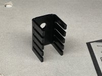
I would like to know if it is OK not to solder the heatsinks to the SLB pcb that have the BD139/140 transistors attached to them. I am hoping for a "yes" answer, as I will have to disassemble a lot of pieces on my build to solder them in place. Thanks for the help,
MM
I would like to know if it is OK not to solder the heatsinks to the SLB pcb that have the BD139/140 transistors attached to them. I am hoping for a "yes" answer, as I will have to disassemble a lot of pieces on my build to solder them in place. Thanks for the help,
MM
Thanks Vunce,
I built these 2 dual rail SLB's quite awhile ago using the larger SK104 type heat sinks. I was hooking up the grounding cables and cables from the SLB to the AN amp board and I noticed that I have not soldered the SK104 heat sink posts to the SLB board.
I am getting ready for a power up, and I am wondering if soldering of the heat sinks to the pcb is mandatory?
MM
No, my Myles.
But if you do solder the heatsink in, be aware that metallic side of the transistor connects to them and the solder point on the pcb must be UNCONNECTED to the rest of the circuit. It should be galvanically isolated.
Hugh
But if you do solder the heatsink in, be aware that metallic side of the transistor connects to them and the solder point on the pcb must be UNCONNECTED to the rest of the circuit. It should be galvanically isolated.
Hugh
Thanks for the explanation Hugh. I looked up what galvanic isolation is, and why it is used. I looked at the circuit layout posted by X in post #1, and it looks like there is no direct connections to the heat sink pins.
Anyways, I am just glad that I do not have to remove the SLB and their heat sinks just to solder the heat sink pins. Pretty tight fit in my enclosure. I am planning to post a picture when I have it ready for power up.
Hope you are enjoying your winter,
MM
Anyways, I am just glad that I do not have to remove the SLB and their heat sinks just to solder the heat sink pins. Pretty tight fit in my enclosure. I am planning to post a picture when I have it ready for power up.
Hope you are enjoying your winter,
MM
- Home
- Group Buys
- The SLB (Smooth Like Butter) Active Rect/CRC/Cap Mx Class A Power Supply GB