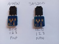
Hello X and other builders. I am having a brain teaser with the dual rail SLB. Not with the actual schematics or layout, but with these 2 little helper boards I have purchased.
I would like to use a 4 pin molex box adapter with these blue helper boards.
Could some one tell me what the numeral 1 on the blue boards signifies ?
Am I correct in thinking that the molex box on the blue boards should be C-C-E-B starting from the upper left corner of the box proceeding clockwise ?.
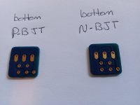
I am also attaching a pic of the bottom of each of the blue heiper boards to hopefully explain my thinking about the molex pins.
Thanks a lot for the help.
MM


Use your DMM to. confirm, but just by looking at the traces, it seems to signify the pad corresponding to pin 1.Could some one tell me what the numeral 1 on the blue boards signifies ?
Thanks IAIMH,
So for the N-BJT board using BCE: In the molex box 1 is B. Proceeding CW from 1 it is E, E, C
So for the P-BJT board using BCE: In the molex box 1 is B. Proceeding CW from 1 it is C, C, E
I don't know why the difference, but will be aware when running wires from the molex box to the SLB.
Thanks for the hint.
MM
Hey everyone,
Read that for the newer version of the SLB dual rail I need to order vertical moles connectors J5 and j6. Mini fit plus hcs46015. Are these the correct ones? Also, I’m using the mouser BOM. Is the cart already doubled for the dual rail? The BOM pdf doesn’t seem to match the board. I’m just a little confused!🙂
Read that for the newer version of the SLB dual rail I need to order vertical moles connectors J5 and j6. Mini fit plus hcs46015. Are these the correct ones? Also, I’m using the mouser BOM. Is the cart already doubled for the dual rail? The BOM pdf doesn’t seem to match the board. I’m just a little confused!🙂
I gotta say, having just built and tested one of these, that the slikscreening is incredibly good -- almost idiot proof. (Though I'm probably just the idiot to mess up on the second one.)
Hi
i am getting 43v under no load, ned to get it down to 36v to use it with my vfet (i have no idea what i'm doing😀👍)
i have asked TungstendAudio, but didn't answer back

i am getting 43v under no load, ned to get it down to 36v to use it with my vfet (i have no idea what i'm doing😀👍)
i have asked TungstendAudio, but didn't answer back
or will this apply ? So i will get ~36v under loadIt could work, I personally would use 300VA but if you have them already, why not. The way to calculate this is to start with the no load voltage and start subtracting drops and losses.
22v is 31v no load. For a 200va trafo running about 2A I would guess about 5v sag. Another 3v drop across SLb is 8v total. 31v -8v = 23v. Should be ok.
160va trafo
amp ~ 1,7amp draw
You will get no more than 3-5v drop in SLB. Maybe 2-5v drop from current sag under a class A load. Thats 5-10v depending on circumstances. Run higher bias current to drop it more?Hi
i am getting 43v under no load, ned to get it down to 36v to use it with my vfet (i have no idea what i'm doing😀👍)
i have asked TungstendAudio, but didn't answer backView attachment 1313863
Use high current diodes in series as voltage droppers. 10x0.6v is 6v drop.
Like This ?Use high current diodes in series as voltage droppers. 10x0.6v is 6v drop.
i only ned to drop ~2v
Why not use larger resistors in the CRC? This would provide more attenuation of high-frequency crap.Use high current diodes in series as voltage droppers. 10x0.6v is 6v drop.
One of those two possible options results in significantly higher output impedance at deep bass frequencies. Many designers prefer power supplies with low output impedance.
i have tested with a 2 ohm resistor at R2,R3, then i get 35,7v under load.
going to test with 1.8ohm when delivery form digikey arrive
Will the output impedance increase significantly?
going to test with 1.8ohm when delivery form digikey arrive
Will the output impedance increase significantly?
Using 2R total resistance for the sum of R2 & R3 will require a 50W rated resistor or two 25W in series for a single rail SLB powering two VFET amp channels.
- Home
- Group Buys
- The SLB (Smooth Like Butter) Active Rect/CRC/Cap Mx Class A Power Supply GB