Hi X, while ordering the parts for two dul-rails SLBs, I couldn't find the heatsink that is specified in the BOM (AAVID 531192B02500G). As there is no further specification in the BOM, I'm guessing which alternative partnumber would fit. Do you have som specs for it: size, thermal transfer? Would part number 531102B02500G (mouser) fit?
Thanks for your help.
Christophe
Thanks for your help.
Christophe
Hi Christophe,
The BD139/140 BJT's do not get hot, you can use a small clip/bolt on heatsink. (I’ve even run them naked in the SLB😁)
https://octopart.com/577202b00000g-aavid+thermalloy-59858
The BD139/140 BJT's do not get hot, you can use a small clip/bolt on heatsink. (I’ve even run them naked in the SLB😁)
https://octopart.com/577202b00000g-aavid+thermalloy-59858

Thanks Mark, but the AAVID datasheet doesn't list 531192B02500G. That's why I'm asking.
I got the AAVID datasheet from the mouser site and checked it already. Unfortunately, there's no indication for that number.
I got the AAVID datasheet from the mouser site and checked it already. Unfortunately, there's no indication for that number.
Thanks Mark and Vunce for chiming in.
The heatsink hardly gets hot and even a small stamped aluminum bolt on fin works.

The heatsink hardly gets hot and even a small stamped aluminum bolt on fin works.
They said that wood case has safety problem.
I've move my SLB in a wood case to a aluminium chassis.
I've move my SLB in a wood case to a aluminium chassis.
Attachments

Hello!
Asking for some help with a possibly fried SLB. I wish I could say I was in a drunken stupor.
I first powered my SLB without the leads plugged in, then again but I forgot to insulate the mosfets while they were on something connected to ground -_-.
I installed the mosfets, put some pads under them, and with power the led's still turn on, but now I'm reading +-1v from the output spades and the pots have no effect.
I didn't get any funky smells or see any burnt looking components, so I'm not getting much in the way of visual cues as to what I killed.
Does anyone wiser than me have advice on what I might have fried and where to poke around to figure out what I messed up?
Thanks!!
Did you power it with a load (that is, amp connected that draws a lot of current)?
If no load, turning it on without the power BJT connected is ok (it’s not a MOSFET).
Running it without an insulator pad would cause a short but not through the junction.
What I suggest is that you take a DVM and measure the voltages relative to ground at all pins of all actives and write it down. Preferably, print out the schematic and mark the voltages in red ink. Take a photo of that and post here so we can help debug. A few closeup photos would help too.
What are the trafo voltages? Are you getting rectified Dc at the output of the active bridge?
What is upstream DC voltage after CRC?
I didn't have any load connected when I made those blunders.
I started measuring and I realized that I had my DVM on too low of a setting -_-;;. Now I know what it means when i get a perfect 1v... it reads a steady 30v when on the proper setting.
I built some f4's to go along with the supply and the led on that board turns on when -v and gnd are connected, but turns off when v+ is connected as well. I'm guessing my error is somewhere on that board.
Thank you!
Hi X, Vunce, other builders,
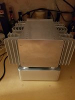
I would prefer to keep the dual rail SLB boards in a position where the caps are vertical, and would like to attach the transistors and the board to a heatsink. The heatsink I have in mind for the psu is an " aluminum slab with an area just slightly larger than the psu board ". No fins on the al slab. The al slab is 3/8" thick. So idea is to bolt this slab to the chassis base and use 1/4" standoff for the board, and attach the transistors to the surface of the aluminum.
So, do you think this is enough sink for the 2 power transistors?
I have the aluminum already from years ago, so would like to use it up. If needed I can add some 1/4" thick copper slab to the aluminum and mount the transistors to the copper. Copper is 1/4T 7"L x 2"W, and can be cut easily.
Comments and idea's are welcome.
Cheers
The above is a pic from my NPXP, when I had the Aleph J. Each Aleph J draws roughly 100 watts/ch and a bias current ~2A/ch (+/- 24V supply). That being said my front panel in this 5U (10mm thick which is roughly 3/8 inch thick) reached about 40 degrees C (some of this temperature rise I am sure is bleeding over from the Aleph J boards themselves!). You’ll see the panel is a bit bigger than the outer edges of the BJT transistors in the capacitance multipliers which will get warm but not hot.
As such, much of this depends on the LOAD you are imposing on the SLB supply board.
For what amplifier design is this for?
Best,
Anand.
Thanks Anand. It is for the Alpha Nirvana. Will be using CPU coolers for the amp transistors. I think the AN operates on a +/- 27V supply and about 1.7A x2 for a total of 92W/ch pretty close to your 100W per channel. It will be dual mono, so chassis will be large.
Having the big caps hanging like that makes me nervous, hence the preference of mounting flat on the aluminum slab.
Cheers
Having the big caps hanging like that makes me nervous, hence the preference of mounting flat on the aluminum slab.
Cheers
Thankfully the Mundorf’s have a very nice adhesive helping them stay on the board (and thankfully so does the solder!). I’ve had no issues personally. Moreover, when you mount vertically, convection helps in keeping the transistors cool.
An example that is more like what you want is from Vunce in his Aleph 30 build
Best,
Anand
An example that is more like what you want is from Vunce in his Aleph 30 build
Best,
Anand
I have a tube of the RTV silicone that could be used for adhesive. Will have to see if it is OK for the caps. Vunce's build is interesting also. Is your adhesive underneath the cap or spread around the circumference of the cap bottom / pcb making a seal? Hard to tell, your build is so neat/impeccable work. I have a lot of thinking to do about placement of boards, coolers, etc inside the enclosure. Just trying to get a bunch of boards built first. Appreciate your idea's.
It’s spread around the circumference of the cap bottom making a seal. It’s actually integral to the design of the capacitor and meant for unusual mounting positions. Many manufacturers use RTV silicone without issue. Unless you expect the amplifier to be in a highly vibrational environment…
Thanks for the kudos, I find my builds sloppy compared to most folks on diyaudio.
Best,
Anand.
Thanks for the kudos, I find my builds sloppy compared to most folks on diyaudio.
Best,
Anand.
Thanks for the info. Would you supply me with the name of the adhesive that you use. May try to find it around my area.
Cheers,
Myles
Cheers,
Myles
- Home
- Group Buys
- The SLB (Smooth Like Butter) Active Rect/CRC/Cap Mx Class A Power Supply GB