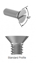
You could try (1) removing the pan head machine screw and replacing it with a flat head screw (triangular silhouette); and then (2) inserting the screw from the back, so the nut is on the TO-220 side of the assembly, and the head is on the trimpot side. This may reduce the overhang enough, to be able to access the trimmer's adjustment slot.
_
_
Attachments
Yup, what Anand and Mark said 
….or just omit the large heatsinks altogether they are not needed. Use the small aluminum "finger” bolt on heatsinks for piece of mind.
….or just omit the large heatsinks altogether they are not needed. Use the small aluminum "finger” bolt on heatsinks for piece of mind.
Also, such large heatsinks on those small TO126 BJTs are not needed. Small stamped aluminum ones that look like a comb can work fine. They will use less board space and cost less.
Good idea by Poseidonsvoice to flip the pot.
Good idea by Poseidonsvoice to flip the pot.
Good solution, Anand. It merely means the screw direction is reversed; CW is the new CCW.
Hugh
Hugh
Hi, I need an alternate for C21 and C22, EEU-FS1H221LB. What are the important parameters for that part? Is there a particular part in stock at mouser that is recommended? Also, I can't find the LT4320IN8#PBF part is there an alternate? I can find LT4320IN8-1#PBF, which looks the same but is good DC-600mhz vs the original which is good DC-60mhz. Thanks for the help
You can use almost anything for C21/22, choose your favourite. Perhaps AN Kaisei of same spec from HFC?
Last week Mouser UK had plenty of LT4320. I've a couple of spares, if you get desperate PM me
Last week Mouser UK had plenty of LT4320. I've a couple of spares, if you get desperate PM me
LT4320IN8-1#PBF is fine to use.
Check Arrow Electronics for stock. They have great prices sometimes.
Check Arrow Electronics for stock. They have great prices sometimes.
Thanks for the quick responses. Would the onsemi/fairchild parts work for Q10 2sk1943 & Q12 2sc5200?:
https://www.mouser.com/ProductDetail/512-2SA1943OTU
https://www.mouser.com/ProductDetail/512-2SC5200OTU
I think that would be the last I need.
https://www.mouser.com/ProductDetail/512-2SA1943OTU
https://www.mouser.com/ProductDetail/512-2SC5200OTU
I think that would be the last I need.
https://www.mouser.com/ProductDetail/Toshiba/2SC5200-OS1F?qs=B6kkDfuK7/DnzN093qetFQ==
Also in stock, and half the price.
I've also had good luck with LCSC (daughter company of JLCPCB).
https://lcsc.com/products/Bipolar-Transistors-BJT_326.html?keyword=c5200
Also in stock, and half the price.
I've also had good luck with LCSC (daughter company of JLCPCB).
https://lcsc.com/products/Bipolar-Transistors-BJT_326.html?keyword=c5200
I have a pair of DR white solder mask with ENIG boards.
Is this still the latest / matching BOM?
I'd like to avoid CDE/Panasonic caps - the larger caps (C7,8,13,14) are easier to substitute (Mundorfs will fit), but what are the best options for C15/16/17 &19 and the two smaller C21/22?
I presume it's just a case of stuffing, slowly add power and hope nothing gets fried?
Where's the schematic for stuffing?
Is this still the latest / matching BOM?
Edit June 5, 2019: Md_Stryker made a Mouser shopping vart/BOM for SLB v1.2 here. Please do not modify it - copy to your own project first!
The SLB (Smooth Like Butter) Active Rect/CRC/Cap Mx Class A Power Supply GB
I'd like to avoid CDE/Panasonic caps - the larger caps (C7,8,13,14) are easier to substitute (Mundorfs will fit), but what are the best options for C15/16/17 &19 and the two smaller C21/22?
I presume it's just a case of stuffing, slowly add power and hope nothing gets fried?
Where's the schematic for stuffing?
I am in the process of changing over my two AN stereo amps to 5RU Modushop heatsinked cases - instead of the active cooling which I chose first up. (The noise of 4x fans at a fairly close listening distance - even though they were Noctua fans - was something I decided I couldn't cope with. 🙁 )
This re-housing also means I can now have my SLB boards mounted horizontally - as well as the AN boards ... which means I can now access the pots on the SLB boards which alter the DC rail voltage & ripple.
So my question is ... is there a trade-off between lowering ripple and increasing the DC rail voltage?
IE. does adjusting the pots to increase the DC voltage - increase the ripple ... or decrease it?
Thanks,
Andy
Hi Andy,
There is less than 1V of adjustment with the pots. Just trim them so output voltage is the same for both rails.
There is less than 1V of adjustment with the pots. Just trim them so output voltage is the same for both rails.
Hi Andy,
There is less than 1V of adjustment with the pots. Just trim them so output voltage is the same for both rails.
Sure, V - that's what I did the first time around (match the DC rail voltages).
But somewhere in this thread is a post which suggests turning the pot also influences the amount of ripple on the DC rail - so I was interested to know whether the benefits of those pots are synergistic (increasing the voltage decreases the ripple) ... or antagonistic (increasing the voltage increases the ripple).
Andy

The higher the voltage drop, the less ripple you get on the output and vice versa.
Aah, OK - so'antagonistic'! 🙁
Thanks, X.
Hi Andy, if you want to get into the details there is an RC circuit feeding the pot and associated resistors that gets to the average of the voltage at the input of the pass transistor. Think of the signal there being a DC value with the ripple superimposed on it above and below the average. The ideal output would be the highest voltage that is just below that average and the low point of the superimposed ripple. The pot is intended to allow you to adjust for that value. Note that the ripple before the series pass will increase with load on the supply. Also note that the pot is not intended to have full adjustment range of the DC voltage.
- Home
- Group Buys
- The SLB (Smooth Like Butter) Active Rect/CRC/Cap Mx Class A Power Supply GB