Hi Ripcord,
Thanks for considering the SLB. The chipamp LM1875 is a Class AB amp and although I would like to say that all amps can benefit from an ultra low ripple PSU, most Class AB amps have very good power supply ripple rejection (PSRR) built in to the design. If you have an SLB already, go ahead and use it like a clean bench lab supply for testing. The background noise and hum will be non-existent on any amp (ground loops on the input signal, notwithstanding). But to make one specifically for this is overkill. Also, larger Class AB amps like a lot of peak current draw and so a plain CRC or even all-C’s PSU is what is ideal for them.
But if you have one - no harm to use it. Don’t buy one for this project unless you are afflicted with regulitis electronicus. 🙂
I guess I have poor salesmanship - not recommending my own product.
Trying to fit a SLB-single rail in a 100x100mm board. The connections carrying the main current should be thick enough (even doubled on a 2-side board), which ones should I care about?
If you are making your own, is it because you want to squeeze it under 100mm square to save on manufacturing costs or is your physical space limited?
I would say it’s not worth making your own when you can just buy the 2mm thick 2oz copper and ENIG board ($18 for gen1) for less than it would cost to make 5 of your own boards.
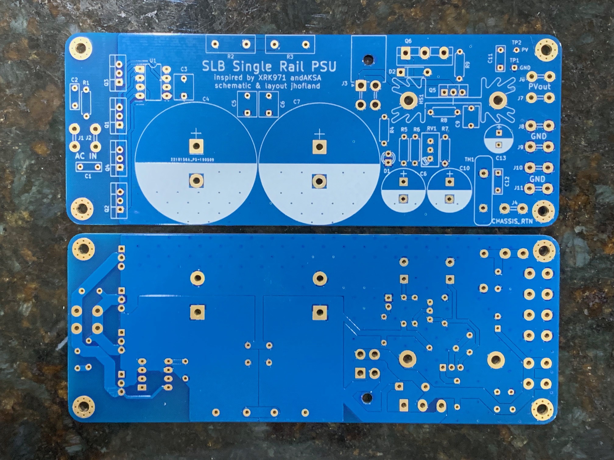
The thick traces are the ones carrying current. So from AC in to CRC, to cap Mx BJT (collector and emitter) and then out. Probably not necessary to do double sided via stitching for the traces. 4-5mm wide 2oz copper should be more than sufficient. Just look at photo to get idea:
I would say it’s not worth making your own when you can just buy the 2mm thick 2oz copper and ENIG board ($18 for gen1) for less than it would cost to make 5 of your own boards.
The thick traces are the ones carrying current. So from AC in to CRC, to cap Mx BJT (collector and emitter) and then out. Probably not necessary to do double sided via stitching for the traces. 4-5mm wide 2oz copper should be more than sufficient. Just look at photo to get idea:
Thank-you for your reply xrk971,
I obviously checked first on etsy. It's not for now, plan for future builds.
There is a mix of several reasons to try this, including high shipping fees from US to FR, some good deals for boards within 100x100mm and adapt the layout to some components.
I obviously checked first on etsy. It's not for now, plan for future builds.
There is a mix of several reasons to try this, including high shipping fees from US to FR, some good deals for boards within 100x100mm and adapt the layout to some components.
Link?
What is the link of this site to compare prices of components?
Wondering if it works also for companies outside of the US.
Thanks.
If you get rid of...
What is the link of this site to compare prices of components?
Wondering if it works also for companies outside of the US.
Thanks.
Just try to keep the power trafo and any AC mains lines far away from the Edcor transformer as possible. If a monoblock, power trafo closer to opposite sidewall even. Use mu-metal on the Edcor. Use star ground topology with a single tie point on the chassis for all grounds from the individual boards.
I do have your schematic for recommended wiring/grounding for the M2X and also have the material for shielding the Edcor.
I have read that this board borrows a couple of volts and the drawing for stereo boards recommends a 3222.
Would a 3220 be a good compromise for a single board?
Would a 3220 be a good compromise for a single board?
need help
Just ordered 2 dual rail SLBs for M2x full mono project. Looking for best BOM with any recommended adjustments. I have Michael's #306 post but don't know if that is current due to EOL or supply issues and/or Covid.
Thanks,
Don
Just ordered 2 dual rail SLBs for M2x full mono project. Looking for best BOM with any recommended adjustments. I have Michael's #306 post but don't know if that is current due to EOL or supply issues and/or Covid.
Thanks,
Don
Hi DonHughes
As far as the BOM goes, the official one is here on post 135:
The SLB (Smooth Like Butter) Active Rect/CRC/Cap Mx Class A Power Supply GB
The shopping cart by MD Stryker appears to be current and all in stock at Mouser:
Mouser Electronics
Please check your Etsy PM's - I think you orderd the single rail by mistake.
What is the dropout voltage of the SLB.I mean I have an F6 amp that runns on +-23v
What voltage will I have with these regulators?
What voltage will I have with these regulators?
.....What voltage will I have with these regulators?
If you were swapping from a conventional type PSU to the SLB, you will lose approximately 2-3v. In your case, the F6 will see 20-21vdc.
The SLB has no type of regulation built in, it will vary with mains voltage.
How do I adjust the potentiometer thats on the pcb?
Edit:Can one SLB take 2 channels F6?
Edit:Can one SLB take 2 channels F6?
Last edited:
One SLB can power two F6 or F5/M2/M2X etc. as each can provide up to 5A continuous current. The on board pot doesn’t do much. We really should have just used a fixed resistors there. There is about 1v of adjustment but that adjusts the drop. The larger the drop, the higher the ripple reduction. Ideally you want to increase the voltage of your trafo of starting from scratch. If you retrofit time an existing build with a properly sized trafo, you will lose 2-3v as Vunce mentioned.
If you get rid of the active bridge, the diodes will have more switching noise since they don’t switch at zero crossing like the active bridge does. The active bridge is one of the key things that makes this PSU one of the ultimate low noise and low ripple PSU’s for Class A amps.
A version with SMT MOSFETs would cost less and be more compact but folks wanted a TH version that is easy to DIY.
For SE Class A amps where there is very poor PSRR, the inherent low ripple and low noise in the SLB is one of the key ingredients to making the amp sound good. There is a saying that goes something like “75% of the cost of Class A amp is in the power supply”.
Last edited:
- Home
- Group Buys
- The SLB (Smooth Like Butter) Active Rect/CRC/Cap Mx Class A Power Supply GB