GB status update - Please review for accuracy and let me know if I made a mistake:
Thanks for all the great interest. I will post the Gerber image and BOM for the SLB-SR shortly as soon as I get the Gerbers from Jhofland.
baswamin - 2 boards - Paid
meanie - 2 boards - Paid
jwjarch - 2 boards - Paid
gary s - 2 boards - Paid
nautibuoy - 2 SLB boards - 2 SLB-SR boards - both Paid, ship together
antoniopf1972 - 2 boards - Paid
ravid - 2 boards - Paid, Simple PSU Paid, ship at same time
Gricko - 2 boards - Paid
poseidonsvoice - 2 boards - Paid
Bkdog - 2 boards - Paid
Jazzfan - 4 boards - *Invoice sent*
yoaudio - 2 boards - Paid
van of monks - 2 boards - *Invoice sent*
Wtl - 4 boards - Paid
cerole - 2 boards - Paid
s610adam - 4 SLB - 6 SLB-SR - Invoice sent
pbergstrom - 2 boards - *need PayPal address*
ferret - 2 boards - Paid
Roundtoit - 2 SLB boards, 2 SLB-SR boards - Invoice sent
Tubesguy - 1 SLB board - Paid
Kokanee - 8 boards - Invoice sent
Arthur - 10 boards - Please send Paypal address
Thanks for all the great interest. I will post the Gerber image and BOM for the SLB-SR shortly as soon as I get the Gerbers from Jhofland.
Last edited:
Btw folks, I received a question from a member who wants to use this as a PSU for a 100w Class A Babelfish Aleph J X Pass DIY amp that draws 7A continuous current. Hugh says that this can still work with low ripple by replacing the BD139/140 with a BD679/680 Darlington and a few resistor changes. I will post schematic as soon as I get things sorted out but short answer is yes. It was designed initially to handle 5A so 7A is not too far off.
https://www.st.com/resource/en/datasheet/bd677.pdf
https://www.st.com/resource/en/datasheet/bd677.pdf
Last edited:
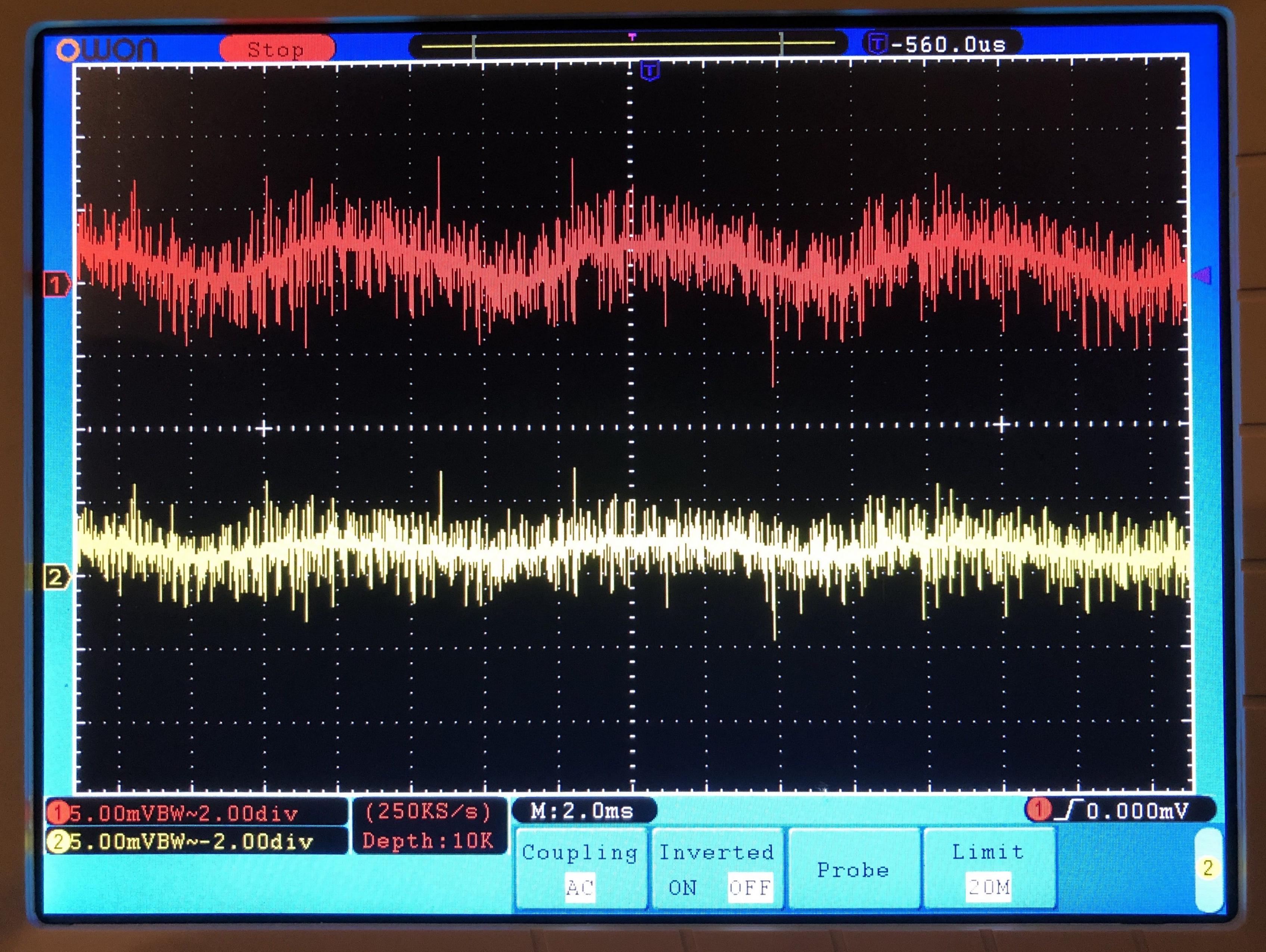
Some independent testing of the SLB topology on an actual SE Class A amp. This data is provided by Vunce and voltage is 37.4Vdc at 3.925A current. Red trace is the 10R for R117 and yellow is 1R5 for R117. Voltage drop on both is about 3.2v. The yellow trace, well it’s smooth like buttah! 🙂
Attachments
Thanks for all the great interest.
Thank you (all involved) for the GB opportunity
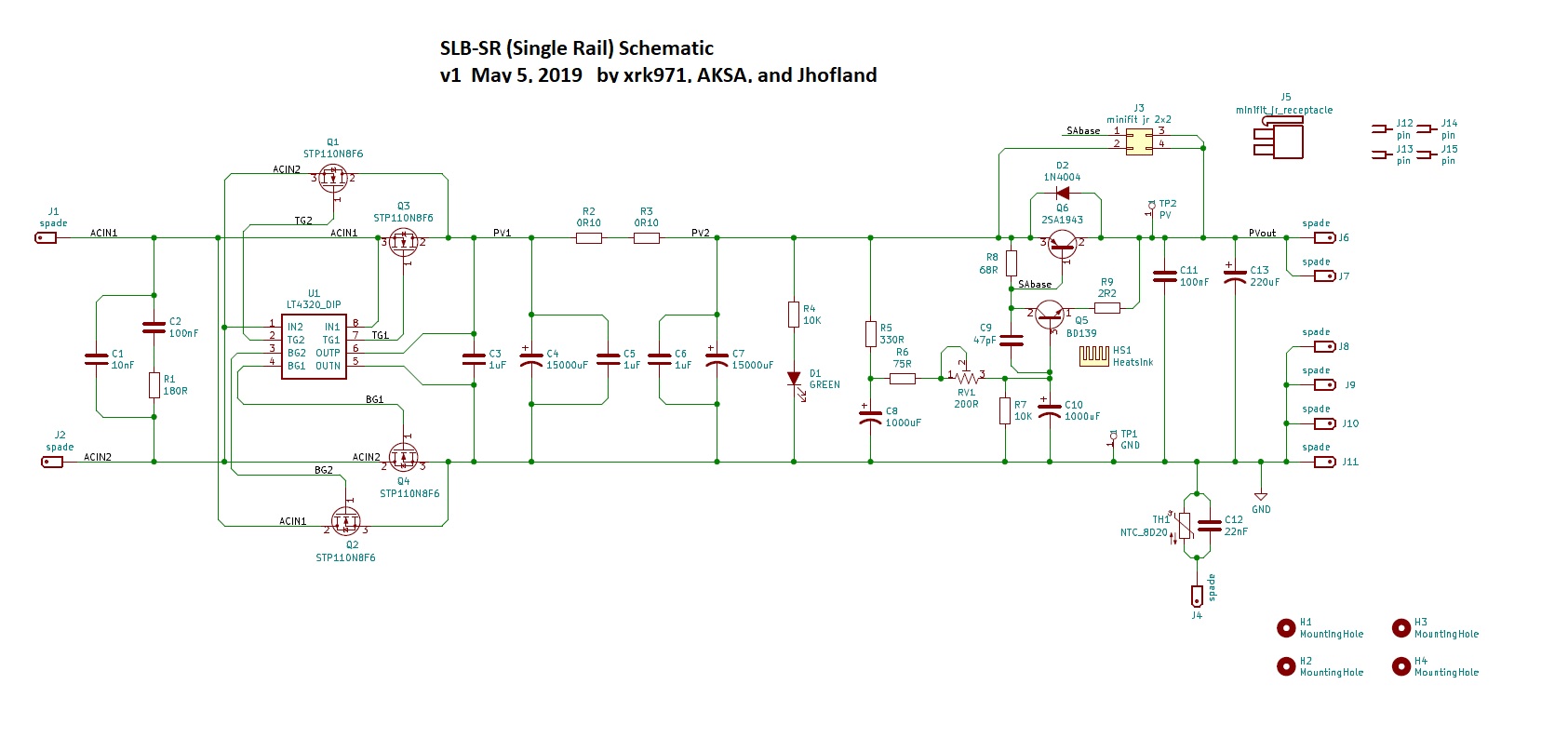
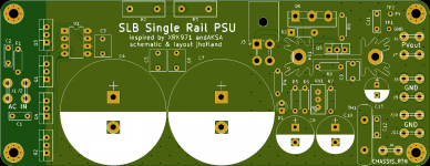
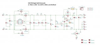
SLB-SR Schematic and BOM
Here is the PCB top view and the BOM in pdf and csv (zipped).
A big thank you to Jhofland for superb layout!


Here is a zoomed in easy to use jpeg of the schematic:
The SLB-SR PCB's are $17ea, and usual shipping for one pair in USA is $5, $10 in CAN, and $15 everywhere else.
Here is the PCB top view and the BOM in pdf and csv (zipped).
A big thank you to Jhofland for superb layout!
Here is a zoomed in easy to use jpeg of the schematic:
The SLB-SR PCB's are $17ea, and usual shipping for one pair in USA is $5, $10 in CAN, and $15 everywhere else.
Attachments
Last edited:
Btw folks, I received a question from a member who wants to use this as a PSU for a 100w Class A Babelfish Aleph J X Pass DIY amp that draws 7A continuous current. Hugh says that this can still work with low ripple by replacing the BD139/140 with a BD679/680 Darlington and a few resistor changes. I will post schematic as soon as I get things sorted out but short answer is yes. It was designed initially to handle 5A so 7A is not too far off.
https://www.st.com/resource/en/datasheet/bd677.pdf
Hi X,
Would the changes to darlington be very stable (not prone to oscillation) and will this require modding the PCB or fit in current TH holes? Would also be nice if the PCB could accommodate the Mega-Fit connectors. They're much easier to play with then fast-tab. See Mouser 538-172065 (2 and 4 connectors).
Thanks
Do
Hi Pinnocchio,
The stability would be handled by increasing the base resistor values by 5x and probably using maybe 3R3 or 4R7 on the R117/R118 feedback resistor. I suppose it needs to be tried first. The recommended Darlington is same size as BD139/40 (TO-126) but pink it’s are reversed so mount flipped around and use smaller stamped aluminum fin heat sinks rather than huge extrude Fischer style AAVIDs (which are overkill). It’s only 250mW dissipation as I recall.
The stability would be handled by increasing the base resistor values by 5x and probably using maybe 3R3 or 4R7 on the R117/R118 feedback resistor. I suppose it needs to be tried first. The recommended Darlington is same size as BD139/40 (TO-126) but pink it’s are reversed so mount flipped around and use smaller stamped aluminum fin heat sinks rather than huge extrude Fischer style AAVIDs (which are overkill). It’s only 250mW dissipation as I recall.
Hi Pinnocchio,
The stability would be handled by increasing the base resistor values by 5x and probably using maybe 3R3 or 4R7 on the R117/R118 feedback resistor. I suppose it needs to be tried first. The recommended Darlington is same size as BD139/40 (TO-126) but pink it’s are reversed so mount flipped around and use smaller stamped aluminum fin heat sinks rather than huge extrude Fischer style AAVIDs (which are overkill). It’s only 250mW dissipation as I recall.
Hi X,
I just looked and pinout seems identical (ECB). Is this something you could test on your side? I don't want to spend 50$USD + components and find out it does not work. What about the mega-fit connector option?
Thanks
Do
Hello !
great stuff...
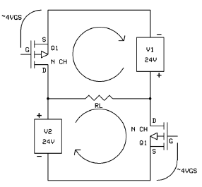
is it possible to use in a circlotron configuration ?
afaik the two regulated side must be floating.
not sure if that is suitable or not with your design.
Thanks !
great stuff...
is it possible to use in a circlotron configuration ?
afaik the two regulated side must be floating.
not sure if that is suitable or not with your design.
Thanks !
My mistake about the ECB pinouts - in that case, no issues there. If you notice, we are using a 4-pin AMP high current quick connect for the slave BJT flying leads. They work ery well. I think that is a great idea to use them for main power in and power out, but then most people already are using spades (FASTON) for their systems so I want to make the transition as seamless as possible.
Maybe in the future I can have an SMT active bridge with all Molex Megafit or AMP quick connectors. It would make for a much more compact and snappy to connect board.
One nice thing about FASTONs is that they are very low profile and have none of the bulk of a plastic shell.
If I have some time, I can test the 7A out but need to order the Darlingtons. Finding a suitable 7A load is tough to find - what is the voltage of the amp you planning to use this in? I can't seem to get the voltage anywhere after spending 20 min looking in that BAJX thread. You would think that is a pretty basic thing to specify in the first 5 schematics presented.
One thing is for sure, it will probably give you at most 10mVrms with the existing BD139/140 circuit as is. That's still a lot better than what a plain old monster CRC that was planned (those are in the 100's mV range). I am trying to get it down to 1mVrms which is why trying the Darlington.
Last edited:
Hello !
great stuff...
is it possible to use in a circlotron configuration ?
afaik the two regulated side must be floating.
not sure if that is suitable or not with your design.
Thanks !
You could use two of the SLB-SR and dispense with the chassis GLB connector to make the supply floating. Simply do not connect the NTC to the chassis ground. Make the GND on the second supply the -ve rail.
My mistake about the ECB pinouts - in that case, no issues there. If you notice, we are using a 4-pin AMP high current quick connect for the slave BJT flying leads. They work ery well. I think that is a great idea to use them for main power in and power out, but then most people already are using spades (FASTON) for their systems so I want to make the transition as seamless as possible.
Maybe in the future I can have an SMT active bridge with all Molex Megafit or AMP quick connectors. It would make for a much more compact and snappy to connect board.
One nice thing about FASTONs is that they are very low profile and have none of the bulk of a plastic shell.
If I have some time, I can test the 7A out but need to order the Darlingtons. Finding a suitable 7A load is tough to find - what is the voltage of the amp you planning to use this in? I can't seem to get the voltage anywhere after spending 20 min looking in that BAJX thread. You would think that is a pretty basic thing to specify in the first 5 schematics presented.
One thing is for sure, it will probably give you at most 10mVrms with the existing BD139/140 circuit as is. That's still a lot better than what a plain old monster CRC that was planned (those are in the 100's mV range). I am trying to get it down to 1mVrms which is why trying the Darlington.
22Vdc - 23Vdc
Jhofland just ran the LTSpice simulation with the Darlington at 7A and it looks good. I will order the Darlingtons and test it out. I will probably use two 100w 8ohm resistors in parallel with a 300VA 32v trafo and probably hope that it can make 28v for 7amps and 200w dissipation over 4ohms. The Darlington will have an added 0.6v drop so we are talking closer to 3.6v drop total now.
Jhofland just ran the LTSpice simulation with the Darlington at 7A and it looks good. I will order the Darlingtons and test it out. I will probably use two 100w 8ohm resistors in parallel with a 300VA 32v trafo and probably hope that it can make 28v for 7amps and 200w dissipation over 4ohms. The Darlington will have an added 0.6v drop so we are talking closer to 3.6v drop total now.
X,
What are we expecting the pass transistor to dissipate over 7A and 23V output?
Thanks
Do
Voltage at output doesn’t matter. 7A x 3.6v drop is 25w. I would suggest a CPU cooler with a Noctua silent fan to handle the 50w from both rails. Much more compact than a 50w passive radiator. One good thing is no heat from the bridge and the bridge doesn’t have the 1.2v drop like a silicon diode full wave bridge, which would have been 8.4w dissipation right there.
Last edited:
You could use two of the SLB-SR and dispense with the chassis GLB connector to make the supply floating. Simply do not connect the NTC to the chassis ground. Make the GND on the second supply the -ve rail.
not sure if we are on the same page.
i am speaking about this topology
i don't quite understand what -ve you are talking about.
Thanks !
M.
Yes, I know what a circlotron is, I think you need to get two of the SLB-SR's and then put the +ve output connected to the speaker load and the -ve end to the MOSFETs. Don't connect the NTC or chassis GNDs.
Yes, I know what a circlotron is, I think you need to get two of the SLB-SR's and then put the +ve output connected to the speaker load and the -ve end to the MOSFETs. Don't connect the NTC or chassis GNDs.
ehehe 😱
I wasn't suggesting that you didn't know. just to be sure we are talking about the very same application.
anyway... seem legit
Every different application other than a 4A 37V SE amp which this is intended for DOES require a redesign. Higher current, lower voltage, fully floating supplies, this requires careful redesign...... be aware that you might be asking for a custom design for your application, and this might be too much to ask of X because he is focussing on HIS application. If you want to redesign, go for it, but it's then YOUR design. It can be done of course, but it has to be prototyped and tested and that is your task for your application. If we do this, we would ask that you document and publicise it here on DIYaudio and no doubt if you find snags we can help you then.
Hugh
Hugh
Thanks, Hugh. The floating circlotron might be kind of tricky I agree. As well as Pinnocchio’s request to use it for a 7A current Babelfish Aleph X, which after Jhofland has spent quite a bit of time on LTSpice simulations we see that it can potentially work but imposed a lot of ripple current in the bulk caps - especially the first one (up to 30A peak). Although with a standard CRC using 66mF / 0.1R / 66mF as suggested by the designer of the BAX, those two 33,000uF caps in the first stage would be undergoing similar peak ripple currents, perhaps even more.
Since the 7A case is so far removed from the norm - I think it’s up to the user to try it out - we can provide suggestions. Even the stock configuration with BD139/140 can work quite well. Just change the two 5W 0.1R KOA BPR for a single 0.1R 25w cement filled one, and use 22,000uF 25V bulk caps.
The case of the +/-24v 1.25A or 2.5A Class A PSU though is not a problem.
Last edited:
- Home
- Group Buys
- The SLB (Smooth Like Butter) Active Rect/CRC/Cap Mx Class A Power Supply GB