Neil Peart!!!!!! I'm going to miss, him. I gave the J2 a serious workout tonight... sounded great faking some hard hitting drums.
There is one other factor here and that is the orientation of the BJT if it were to be mounted on the board. Can you confirm that the heatsink surface would be facing outward off the board and not inward, toward the board.
Yes, that’s correct. You can also tell by the pads: square is pin 1 (Base).
Is that the same for all transistors/mosfets on your PCBs, X?
Andy
Hello,
I am building a dual mono SLB / Alpha 20. This will be my first non First Watt standard power supply power amp. The standard First Watt power supply uses CL-60s and line rated capacitors before the transformers. I am guessing that the CL60 is used to limit in-rush current. I don't know what the capacitors are for (line noise?). Are CL60s and line capacitors recommended for the SLB as well?
Thanks,
Alan
On SLB, you can use a CL-60 or 8D-20 at TH1. It is for a safety ground to protective earth and chassis. It serves in this case, as a ground loop breaker (GLB).
On the primary side of the main power transformer, I use an NTC 8D-20 in series with mains connection to the primary, after the main switch and fuse. This is as a soft start. It is about 8ohms cold and as current flows it heats up and is about 0.5ohms hot. That prevents a big surge into the trafo.
The secondaries of the trafo connect to the AC inputs of the SLB. There is a snubber capacitor and resistor there. You can fine tune that with an oscope and adjust the resistor to get the lowest noise. It’s probably not so critical here because the active bridge switches at the zero crossing so there is inherently no noise associated with traditional diode switching at 0.6v.
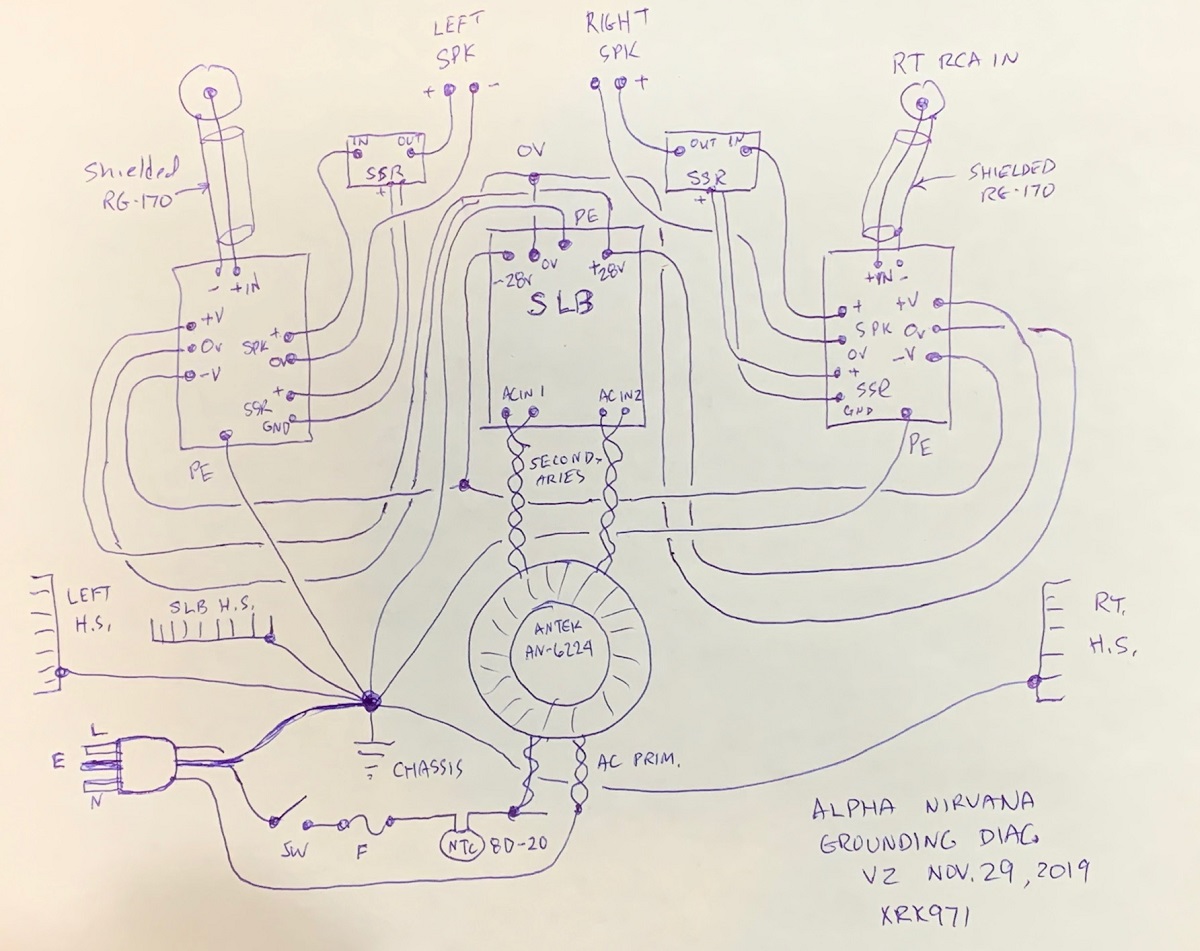
Here is an entire amp hook up diagram for the Alpha Nirvana. The Alpha 20 is similar (doesn’t have GLB’s on each amp board), but you can see where I use NTC 8D-20’s. Note that CL-60’s are also ok here. I use 8D-20’s because they handle higher current and cost a bit less.
On the primary side of the main power transformer, I use an NTC 8D-20 in series with mains connection to the primary, after the main switch and fuse. This is as a soft start. It is about 8ohms cold and as current flows it heats up and is about 0.5ohms hot. That prevents a big surge into the trafo.
The secondaries of the trafo connect to the AC inputs of the SLB. There is a snubber capacitor and resistor there. You can fine tune that with an oscope and adjust the resistor to get the lowest noise. It’s probably not so critical here because the active bridge switches at the zero crossing so there is inherently no noise associated with traditional diode switching at 0.6v.
Here is an entire amp hook up diagram for the Alpha Nirvana. The Alpha 20 is similar (doesn’t have GLB’s on each amp board), but you can see where I use NTC 8D-20’s. Note that CL-60’s are also ok here. I use 8D-20’s because they handle higher current and cost a bit less.
Last edited:
Thanks X,
Do you have a mouser part number for the 8D-20 you use. I had ordered the part listed in the SLB BOM (8D2-07LD) but it appears to be rated for two amps.
Alan
Do you have a mouser part number for the 8D-20 you use. I had ordered the part listed in the SLB BOM (8D2-07LD) but it appears to be rated for two amps.
Alan
Just get CL-60 (5A and 10ohms) if you are wanting it quick and via Mouser. $2.60 is not bad for quick.
For the future, you could order a bag of 20 from China. It will take a while to get here but I use a lot of these and handy to have this many on hand.
20pcs 8 Ohm 6A Power NTC Thermistor surge current limiting MF72-8D20 | eBay
For the future, you could order a bag of 20 from China. It will take a while to get here but I use a lot of these and handy to have this many on hand.
20pcs 8 Ohm 6A Power NTC Thermistor surge current limiting MF72-8D20 | eBay
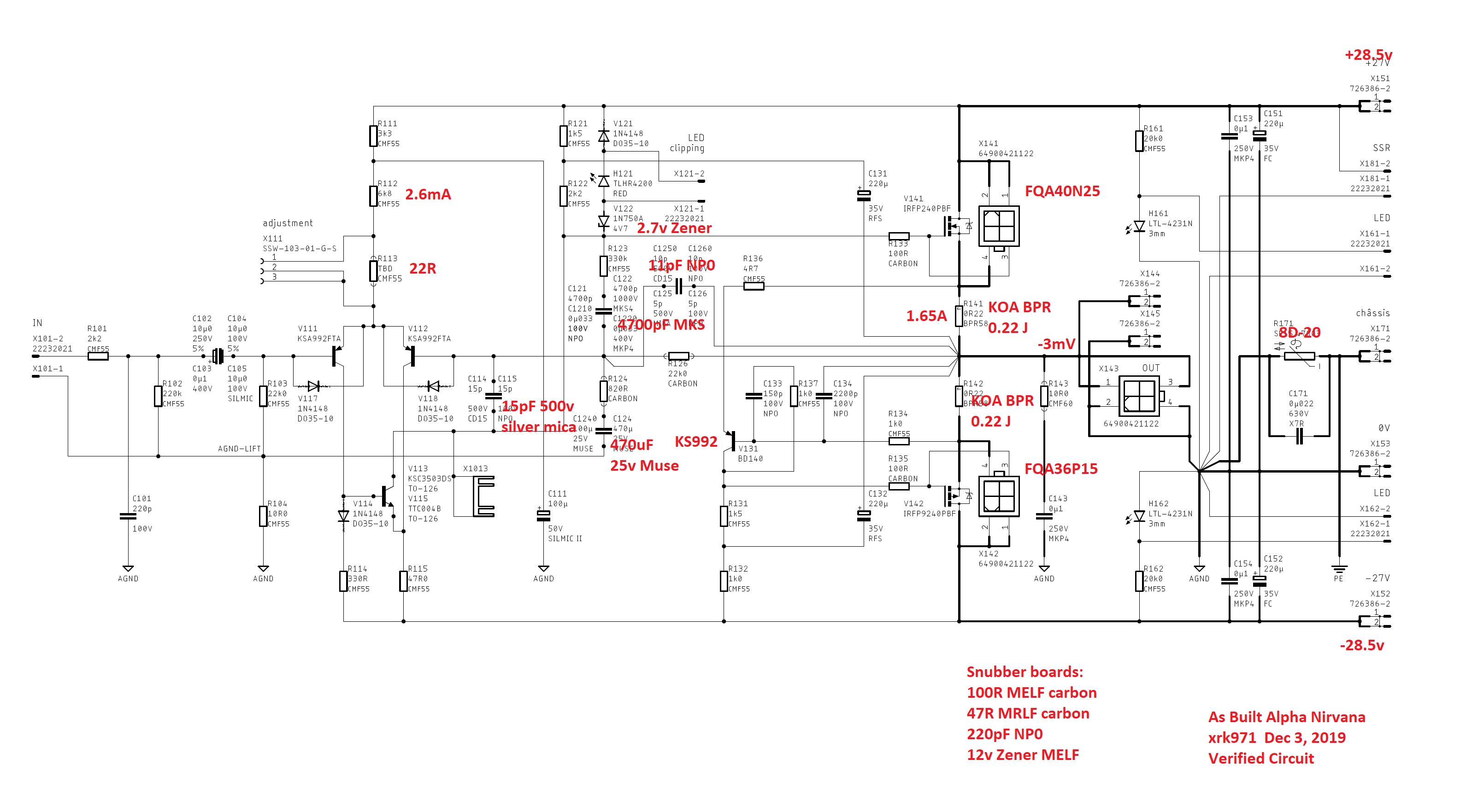
A heads up on the SLB board layout, if it wasn't mentioned before... if you are going to use the BOM heatsinks, you will want to flip the orientation of the one Bourn pot that has the screw facing the heatsink. If you don't you won't be able to access the screw to adjust.
JT
JT
Good point, thanks for the tip. I didn’t do this so have to use a little skinny screwdriver to get around the heatsink screw that goes through the BJT. Only needs to be adjusted once though, thank goodness. I am almost thinking it could just be a fixed resistor as seldom needs adjustment.
Some stuff for us newbs
X144 speaker out + (Pin 1 OR 3 of X143
X145 Speaker out - (Pin 2 OR 4 of X143
Both pins 1-3 are electrically the same
Both pins 2-4 are electrically the same (Easy to see on bottom of board and schematic.)
X181 is called SSR: This is a soft start option to make things easier on components. It prevents them from getting hammered by an initial rush of current when charging caps etc. So SSR would be Soft Start Relay. Which you may or may not use depending on your build.
IF using the SLB (Smooth like Butta) supply then you will see an output labeled Chassis RTN or chassis return. This is the ground loop breaker in case of disaster, so the case doesn't see mains. (Your house AC) Touch the chassis and die sorta thing.
Again, this is just for us new guys and if I have anything wrong please correct it. It's a steep curve for some of us, so I thought I would share some bits that it took me way to long to figure out, but nonetheless enjoyed figuring out.
So we have some marked Chassis return and the ground drawing doesn't show this, but shows PE as does your output board. No worries, these all go to the same point... chassis ground. The designer was simply telling you what that particular path to chassis ground is.
These are just few things, I thought I would share for people working this build, who have limited knowledge. Often the designer knows something front to back and things get abbreviated and are lost on the new people.
I appreciate them putting this stuff out there and they also try to gently encourage you to learn or investigate before asking questions, but sometimes we need a quick answer from those who know because we just spent 20 mins figuring out what SSR meant and Also the 0V. it wasn't until we found the ground drawing that we understood. 🙂 Yes, that would be me, and I felt silly when I finally came across that drawing, but also smiled because I figured it out without having to bother X or the forum with it.
Also, there are times like when I was building the J2 and hitting Jeff with tons of questions because I was scared to burn-up those damn Semisouths (FETS that are rare and very very costly,) also called, "unobtainium, cause you can't find them or cost too damn much."
Last edited:
Hi Thompsontech,
I was a bit confused but now realize you are talking about the Alpha Nirvana amplifier board or schematic as the SLB does not use Xnnn to refer to connections. That’s a JPS64 standard.
X188 is a 2-pin connector to provide DC rail power to the Solid State Relay (SSR) DC protection and speaker turn on delay board. It’s not for the soft start circuit. Soft start is a different thing and is under development. The soft start limits current during initial turn on by passing it through a bunch of power resistors. After a few seconds after things are equilibriated, a solid state relay in the soft start bypasses the resistors to provide full current flow to the main power transformer primaries.
The start up in rush current results from charging the transformer (magnetic energy storage) and also charging the bulk smoothing caps.
Please attach an inline link to the schematic you are referring to when citing specific component parts or connectors on a schematic or drawing. Like this:
It will save me 7 minutes needed to find the cited schematic to understand the question asked. And I might even get the incorrect schematic if there are multiple ones.
Thanks,
X
Last edited:
@X Sorry buddy, this was supposed to be in the AN thread! Can someone move it for us? Yes, I should have known the schematic (your ground schematic) goes right to the speaker and breaks the connection until it has had time to settle... I should have taken more time to examine, before I typed that mess... Ah well, perhaps someone besides me can learn from it.
JT
JT
Last edited:
No worries, I do that sometimes too. If you click on the red exclamation icon, you can request a mod to move it.
Hi X,
For the SLB @ 4A per rail, can you tell me how hot the ideal bridge Mosfets (STP110N8F6) get? Is this with no heatsink or with passive cooling installed? I'll try to reach ~7A and I want some Mosfets that will stay @ max 50 Celcius...
Thanks
Do
For the SLB @ 4A per rail, can you tell me how hot the ideal bridge Mosfets (STP110N8F6) get? Is this with no heatsink or with passive cooling installed? I'll try to reach ~7A and I want some Mosfets that will stay @ max 50 Celcius...
Thanks
Do
Hi Do,
IIRC, those are ultra low 0.0056Ohm RDSon MOSFETs. P=I^2R
7A^2x0.0056ohm or 0.27W. Being TO-220, 0.27w makes them barely warm, say 35C. I wouldn’t worry. How hot does 5.6mOhm 3W resistor get running 7A through it?
Cheers,
X
IIRC, those are ultra low 0.0056Ohm RDSon MOSFETs. P=I^2R
7A^2x0.0056ohm or 0.27W. Being TO-220, 0.27w makes them barely warm, say 35C. I wouldn’t worry. How hot does 5.6mOhm 3W resistor get running 7A through it?
Cheers,
X
If you click on the red exclamation icon, you can request a mod to move it.

Since the post has been replied to, it would interrupt the flow of the thread to dissect it. No harm done.
- Home
- Group Buys
- The SLB (Smooth Like Butter) Active Rect/CRC/Cap Mx Class A Power Supply GB