I have updated the git repository to include additional information and corrections.
It is best to download the new zip file from GitHub - lhquam/SIT3X-Power-Amplifier and unpack it and look at <dir>/SIT3X-Power-Amplifier-master/SIT3X-Power-Amplifier.html in your browser.
It is best to download the new zip file from GitHub - lhquam/SIT3X-Power-Amplifier and unpack it and look at <dir>/SIT3X-Power-Amplifier-master/SIT3X-Power-Amplifier.html in your browser.
More about the (optional) SIT3X Power Modifications:
The additional power supply for the front-end could be avoided by using something like the BA3-FE modified to have 10x gain. However, because the BA3-FE is non-inverting, this would result in positive H2 relative phase in the desired region of A values of the magic P6 pot.
Without actual listening tests, I do not know how much difference it would make.
Maybe Nelson can provide an opinion.
Another important insulator is needed to prevent the mounting screws from contacting the case of the 2SK182ES. I used Digikey part# RPC6397-ND shoulder washers.
Just about ready to start wiring up my SIT-3X (basically a copy of Lynn's original prototype/transformer/heatsinks/fans). The one outstanding issue is finding the properly sized insulators for the 2SK182ES. Any suggestions as to where I might find such a beast?
Just about ready to start wiring up my SIT-3X (basically a copy of Lynn's original prototype/transformer/heatsinks/fans). The one outstanding issue is finding the properly sized insulators for the 2SK182ES. Any suggestions as to where I might find such a beast?
I am glad to hear that you are planning to copy to SIT3X prototype. I knw that it works well. D not hesitate to ask questions.
I would like to hear from any others who are planning to copy to prototype.
I plan to copy your prototype. I happen to have two chunks of Heatsink USA just like you used! I like to follow the tried and true path and once I understand the build better decide if I want a different format.
Russellc
Russellc
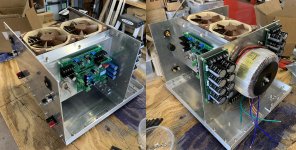
Look familiar?
Certainly does. I haven't yet written smoke test and adjustment instructions. Let me know when you are getting close.
The previous git zip file had problems due to absolute file names in links. I am still learning how to use the Seamonkey HTML composer, and did not realize when it was using relative vs. absolute links. I think it is now fixed in the latest update to the git repository.

Yes, those spectra were for the right channel which has to highest 60Hz harmonic noise levels of the two channels.I don't recall. Are your current numbers similar to the ones of posts
207, 249, 250?

Sometimes while making bench measurements those levels change significantly, both up and down when I rotate the amplifier 90 degrees to 180 degrees. I suspect it is due to the transformer fields affecting wiring used for the measurements.
I don't recall. Are your current numbers similar to the ones of posts
207, 249, 250?
Perhaps misunderstood your question. I had been thinking about grounding issues and forgot that I had been seeking an opinion about second harmonic phase involving the choice of inverting vs. non-inverting front-ends.
The plots in posts #249 and #250 are representative of the behavior of the SIT3X with 44V rails and 1.8A bias.
In post #249 the attenuation level is adjusted for the PFET acting as a CCS at low power levels. This where I have done most of my listening.
In post #250 the attenuation level is adjusted into the pull-pull region where the SIT and PFET are fighting each other. I have not done a lot of listening in the region.
Here is a new chassis that looks like a good fit for the SIT-3X. It has been proposed as an option by Modushop.
Ultimate 4U 500mm Chassis - Who is interested?
It can be done with a different arrangement of the boards and a slightly longer ribbon cable to connect them. Power dissipation should be comparable to the 5U, 400mm deep chassis.
Ultimate 4U 500mm Chassis - Who is interested?
It can be done with a different arrangement of the boards and a slightly longer ribbon cable to connect them. Power dissipation should be comparable to the 5U, 400mm deep chassis.
I have been trying to understand why one of my three FCFE PCBs has much worse PSRR than the others and think I have discovered the answer:
From post SIT measurements, Mu Follower, and amplifier build. This was in response to the discontinuation of the 2SC4793 and 2SA1837 BJTs.
Quote:
Originally Posted by Nelson Pass
It's a generic part, nothing special. I recently used some TIP31 and 32.
I have been using the TIP31C and TIP32C in the SIT3X folded cascode front-end. One of the three PCBs using these parts shows a much higher PSRR (sensitivity to ripple of the rails). I started looking carefully at the SPICE models for the parts and the Early voltage for the TIP parts is about a factor of about 30 lower than for MJE15032/MJE15033, KSC3503DS/KSA1381, 2SC4793/2SA1837 BJTs. With good matches between the Early voltages of PNP and NPN the effects will cancel in this complementary circuit, but an imbalance will degrade the PSRR.
I believe that there are good 2SC4793 and 2SA1837 transistors available on EBay and suggest using them rather than the TIP31C and TIP32C.
Last edited:
Today I replaced the TIP31C and TIP32C with KSC3503/KSA1381 in the FCFE boards. It appeared to help on the PSRR bench measurements on one of the channels. It simplifies the FCFE BOM to eliminate the TIP31C and TIP32C transistors, and double up the KSC3503 and KSA1381 transistors.
Mysteriously, the Vrms of the OS outputs with the inputs shorted changes between my workbench and my listening room. Could the AC mains waveforms be different enough between the two places?
Mysteriously, the Vrms of the OS outputs with the inputs shorted changes between my workbench and my listening room. Could the AC mains waveforms be different enough between the two places?
You might be on the opposite phase in the work shop vs. the listening room (more load on one phase than the other.) Or closer to the main power panel in one or both closer and different load on the phase.
Or planetary alignment.
Rush
Or planetary alignment.
Rush
Today I replaced the TIP31C and TIP32C with KSC3503/KSA1381 in the FCFE boards. It appeared to help on the PSRR bench measurements on one of the channels. It simplifies the FCFE BOM to eliminate the TIP31C and TIP32C transistors, and double up the KSC3503 and KSA1381 transistors.
Would using 2 pairs of 2SC4793 / 2SA1837 instead of TIP31C/TIP32C and KSC3503/KSA1381 work, too?
I guess one would have to figure out the reversed pins, though.
Thanks!
- Home
- Amplifiers
- Pass Labs
- The SIT-3X Amplifier