Does the Antek 1000VA transformer actually have four 35V secondary windings?
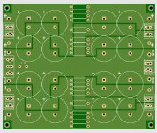
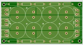
No, that is why the preferred capacitor configuration shares 4 caps per rail in the first stage between channels and splits into 2 caps per rail in the second stage of the CRC filter.
Attachments
Does the Antek 1000VA transformer actually have four 35V secondary windings?
Something I had not considered before. How about stacking 2 toroidial transformers with 1/2 of VA rating of the single transformer? The vertical height would be about 6.2", the diameter decreases, and the Antek price is about the same. Now you have 4 secondary windings and can really have independent power supplies for the 2 channels.
The cap board below would do just fine.
Attachments
Last edited:
That would also be my preferred configuration, because I already have suitable toroids with enclosures. It would also allow me a few more mounting configurations. I was going to use this build as an <cough> "excuse" to purchase a shiny new 1000 VA Toroidy I've had my eyes on. I may still go that route. Either way, If you do choose to offer options, I would order both. It will open up some possibilities.
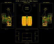
With stacked toroid transformers the 5U 400mm chassis layout looks great. This is definitely the way to go. Having independent power supplies cleans up some grounding issues.
Even though it's for a different amp I stacked mine. Allows for everything in a single enclosure.
Regards,
Dan
Attachments
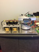
Even though it's for a different amp I stacked mine. Allows for everything in a single enclosure.
Regards,
Dan
This is an impressive structure.
This is an impressive structure.
Should be! It weighs about 40lbs! It's a 1.6kva CLC 60VDC power supply for the Schade amplifier mentioned in this forum.
Regards,
Dan 😱
I word of warning: I have not been able to confirm the accuracy of the thermal resistance quoted for the Store 5U 400mm heatsinks. If anyone out there has a build using them, can you provide the following information:
- heatsink depth (300mm, 400mm, ..)
- heatsink height (210mm for all of them?)
- watts dissipated per heatsink
- temperature rise: T_sink-T_ambient)
I can confirm the dimensions. See attached. Note that there are two heatsinks per side. So, heatsink depth on the 400mm is 2 x 200mm. See pics. Apologies for poor lighting.


Note, the specs for each sink is 0.28C/W. Note my dodoness, in that I don't know if you just cut that in half for two sinks... but wanted to be sure to clarify. Here is the page.
40mm Heatsink Information – diyAudio Store
200 x 40 x 210 0.28C/W
I did a quick Google search, but I am unable to determine how I could measure the last two points. I've read a few posts that state that we should generally "de-rate" them by 25%. However, I truly don't know. If you have a simple way to measure, I'd be willing to give it a go.
As far as I understand, the heatsink C/W is simply proportional to its length. This chart always let me wonder how they calculated (or measured) it because 120 and 165 do not. Probably it's whole enclosure's C/W.
Plasnu - That makes sense. 😀
Ihquam - Thinking about it a bit more... (That's dangerous for me)... I can very easily take the following measurements and provide information about set-up for the amp in the chassis.
Ihquam - Thinking about it a bit more... (That's dangerous for me)... I can very easily take the following measurements and provide information about set-up for the amp in the chassis.
- Bias current and rail voltage => W per device
- Number of devices per heatsink x W per device => Total W per heatsink dissipated
- Temp of devices on package
- Temp of external surface on heatsink at hottest spot
- Ambient temp
As far as I understand, the heatsink C/W is simply proportional to its length. This chart always let me wonder how they calculated (or measured) it because 120 and 165 do not. Probably it's whole enclosure's C/W.
I think Lynn is asking if the C/W is accurate in real life. Looking at the dimensions of the heat sink vs. the claimed C/W, the C/W looks to be optimistic.
Has anyone used this chassis, 5U, and can verify the watts strapped on the heat sink vs. the heat sink delta temperature?
For example a F5 Turbo at 40 volt rails and 2.25 amps = 180 watts per side. This would result in a 25C rise in temperature if the .14 C/W is correct. Can anyone verify that the store heat sinks can support 180 watts per channel and only have a 25 C temperature rise?
Rush
Yes, saw that. Does not include 5U chassis and looking for actual measurements at this time.
Rush
Rush
@Rush, I know exactly what you mean. I bought similar sized heatsinks hoping they work for my amp, but they did not perform as good as this chart. That's why I guessed their chart includes dissipation from the other part of chassis. Maybe serrated fins helps, which suppose to dissipate a little better than flat fins. I don't know how better, though... Let's wait the report from real users.
Last edited:
Plasnu - That makes sense. 😀
Ihquam - Thinking about it a bit more... (That's dangerous for me)... I can very easily take the following measurements and provide information about set-up for the amp in the chassis.
Would that help?
- Bias current and rail voltage => W per device
- Number of devices per heatsink x W per device => Total W per heatsink dissipated
- Temp of devices on package
- Temp of external surface on heatsink at hottest spot
- Ambient temp
Yes, that is exactly what I am looking for. And the measurements of heatsink temperature at the hotspots and near the edges too.
- Home
- Amplifiers
- Pass Labs
- The SIT-3X Amplifier