Global feedback can reduce PS rail noise, but I am not sure about ground noise.
Most of the problem I see appears to be w.r.t. signal grounds, particularly ground loops through the RCA input. I see about 1mV RMS noise (of a Fluke multimeter) with the both RCA inputs grounded, which is only audible with the ear about an inch from the speaker cone. But with very careful care to grounding everywhere, it should be possible to achieve 100uV RMS.
Most of the problem I see appears to be w.r.t. signal grounds, particularly ground loops through the RCA input. I see about 1mV RMS noise (of a Fluke multimeter) with the both RCA inputs grounded, which is only audible with the ear about an inch from the speaker cone. But with very careful care to grounding everywhere, it should be possible to achieve 100uV RMS.
Hi Lynn. Here's my attempt at updating the current list and adding myself. Apologies if I missed anyone:
...
Total of 13 sets so far. 🙂 If I'm not mistaken, a set of boards includes the cap board, correct? Are people requesting an additional cap board for dual mono? Please clarify for Lynn's sake.
The cap board is optional. One design for the dual channel cap board can be cut in half for dual mono. I am looking at different design that cannot be cut in half and would require a different single channel cap board.
I just now saw the PM. I believe that I have found a work-around for generating Gerber files. It isn't perfect, but with some care I believe that I can create correct Gerbers.lhquam, you got my emails and PM ?
just take route I gave you
easy-peasy
nice guy ( I don't want to name him, to avoid unnecessary work on Gerbers ) , he even contacted me again , saying that you didn't wrote
you'll get Gerbers in a minute, that's simple procedure with right software
easy-peasy
nice guy ( I don't want to name him, to avoid unnecessary work on Gerbers ) , he even contacted me again , saying that you didn't wrote
you'll get Gerbers in a minute, that's simple procedure with right software
The cap board is optional. One design for the dual channel cap board can be cut in half for dual mono. I am looking at different design that cannot be cut in half and would require a different single channel cap board.
What ever the cap board format ends up being, my plan was for dual mono, so I will be happy.
Thanks for all the effort,
Russellc
I tried CDE 382LX and it sounds terrible even after 100 hours. Soundstage is bad, and the sound is very uneven.
Perhaps pick something else. Cheers.
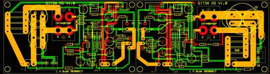
This is an update of the PC board progress. After looking at a number of issues with packaging my existing OS boards on the 5U 400mm heatsinks I was not satisfied about using the OS board in the 180degree rotated configuration. As a result I am laying out a left-to-right mirror image version of that board so the access to pot adjustments and connections to the SIT are acceptable positions. The ribbon cable connections to the FCFE board will be the same and the OS-left +OS-right board pairs will work for either "normal" chassis with heatsinks fins pointing outward, dual mono, or my prototyping chassis with the heatsink fins pointing inward forming a heat tunnel.
I do not expect the overall costs for the board package to increase very much.
I do not expect the overall costs for the board package to increase very much.

Monoblocks:
It should be possible to do monoblocks, with the SIT on one heatsink and the PFET and OS board on the other. But, the SIT gate stopper should be close to the SIT, probably a resistor soldered to the wire from the OS board, with the connection protected by shrink tube, and jumper around the place for that resistor on the OS board.
It should be possible to do monoblocks, with the SIT on one heatsink and the PFET and OS board on the other. But, the SIT gate stopper should be close to the SIT, probably a resistor soldered to the wire from the OS board, with the connection protected by shrink tube, and jumper around the place for that resistor on the OS board.
Hi. Thanks for all the tremendous effort. Please put me down for a set of boards. I don't require the PSU boards though.
Thanks.
Thanks.
Five different PCBs have been ordered in quantities for +/- 25 SIT3X amplifiers. Keeping my fingers crossed on the PCB artwork.
My next effort will be to bring the BOMs up to date.
My next effort will be to bring the BOMs up to date.
Monoblocks:
It should be possible to do monoblocks, with the SIT on one heatsink and the PFET and OS board on the other. But, the SIT gate stopper should be close to the SIT, probably a resistor soldered to the wire from the OS board, with the connection protected by shrink tube, and jumper around the place for that resistor on the OS board.
Understood. I will build as you intended, I don't want to complicate if unnecessary. So make that a regular stereo set with power supply.
Russellc
Just reading about the output caps on the F8, (on the F8 thread linked below,) Nelson said; "Each channel has two parallel 10,000 uF 50V Panasonic electrolytics bypassed by 1.5 uF polypropylene."
First Watt F8
Rush
First Watt F8
Rush
Using unobtainium parts again. That's papa for you. The only 50V 10mF Panasonic electrolytic caps are on the discontinued list. It might be EETHC1H103.
There is enough room on the SIT3X OS PCBs for 2X D<=26.6mm LS=10mm caps or 3X D<=21.6mm LS=7.5mm. They can be polar with V>=16V, or non-polar
Here are some possible output cap alternatives for the SIT3X:
There is enough room on the SIT3X OS PCBs for 2X D<=26.6mm LS=10mm caps or 3X D<=21.6mm LS=7.5mm. They can be polar with V>=16V, or non-polar
Here are some possible output cap alternatives for the SIT3X:
- 3X667-EEU-HD1E103 10mF 25V polar LS=7.5mm D=18mm H=35.5mm Panasonic
- 2X647-UFW1V103MRD 10mF 35V polar LS=10mm D=22mm H=50mm
- 3X647-UFW1E103MRD 10mF 25V polar LS=10mm D=20mm H=40mm (see below).
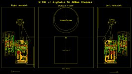
Here is the preferred chassis layout foor the SIT3X using the diyAudio Store 5U 400mm chassis.
The transformer and cap board on the chassis floor are rather tight, but will probably work ok. I prefer this configuration to stacking the cap board on top of the transformer, but that might to ok to with proper precautions.
The transformer and cap board on the chassis floor are rather tight, but will probably work ok. I prefer this configuration to stacking the cap board on top of the transformer, but that might to ok to with proper precautions.
Attachments
- Home
- Amplifiers
- Pass Labs
- The SIT-3X Amplifier