well, now you see - you opened can of (glorious) worms 
I chose to find few nice spots around the rim of can and exploit them
you have no other choice (having math) than to try to mend entire circumference of rim..... but , you must take it easy ......
I chose to find few nice spots around the rim of can and exploit them
you have no other choice (having math) than to try to mend entire circumference of rim..... but , you must take it easy ......
Attachments


...
If there is enough interest, I can do a new run of PCBs and make them and the BOMs available.
I'm interested!
that second one is more of my type
🙂
Are potential builders of the SIT3X ok with the PCB mounting shown in posts #180 The SIT-3X Amplifier and #203 The SIT-3X Amplifier and the PBC layouts below?
Attachments
Last edited:
Operating a push pull pair partly in push push (or pull pull I suppose) is very inefficient, worse than single ended class A. Also, as you say, this does not correspond to the lowest distortion either so there must be a very compelling reason to employ it. What am I missing?
Wacko -voodoo ...
And, yes, with the P6 pot A=1 that is the behavior of the SIT3X, but the distortion is much higher than when operating in the "normal" push-pull region. The harmonic falloff rate is about the same at -15dB per harmonic.
Hi Lynn,
Is it possible to use a longer ribbon cable between the front end and output stage
boards?
Thanks,
Dennis
Is it possible to use a longer ribbon cable between the front end and output stage
boards?
Thanks,
Dennis
Yes. I will soon post some PCB mounting options for a diyAudio Store 5U chassis.
Hi Lynn,
Is it possible to use a longer ribbon cable between the front end and output stage
boards?
Thanks,
Dennis
Can we use other Tokin SIT like 2SK180 /THF 51?
How do we select the SIT for this design ?
thanks
kannan
How do we select the SIT for this design ?
thanks
kannan
Any listening comparisons with other known amps such as SissySIT, Singing Bush etc? One can possibly get an idea of what to hear with different Gate settings of the SIT device in this implementation. Thanks.
Today I have been looking at the H2 behavior of the folded cascode front end (FCFE). This project turned into two circuit development projects instead of only one for the output stage, because of the need (or desire) for a non-feedback, low output impedance front end. Additionally, in order to obtain negative H2 phase for my chosen region of operation of output stage, it was necessary to have an inverting front end and reversed speaker connections to the output. That is how I ended up choosing the folded cascode topology.
Until today I did not realize how difficult it is to adjust the 2nd harmonoic (H2) of the folded cascode. I have played around with at least 2 approaches, both in simulation and the actual build, and discovered that the relative JFET Idss is about the only parameter that have much affect on H2 without causing a big shift in the DC offset of FEOut. In the case of my right channel FCFE build, I can minimize H2 with an output offset of about 4 volts. That might actually be acceptable, but increasing Idss of the J74 JFET or reducing the Idss of the K170 JFET would reduce that offset.
The front end design has been a learning experience for me.
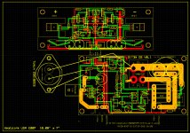
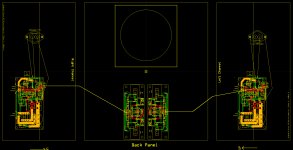
Am about ready to order revised versions of the SIT3X FCFE and OS PCBs. I have made revisions that look to be compatible with installing in a chassis with suitably large heatsinks, such as the diyAudio 5U chassis with 400mm depth. The image below shows right CH heatsink, top-view, and left CH heatsink.
I need to get an idea of how many are interested in purchasing the boards. The first run of 4 each boards will cost me about $360, but will also produce Gerber files that can be used by a lower cost PCB fab facility. The cost will depend on the vender and the quantity ordered.
I need to get an idea of how many are interested in purchasing the boards. The first run of 4 each boards will cost me about $360, but will also produce Gerber files that can be used by a lower cost PCB fab facility. The cost will depend on the vender and the quantity ordered.
Attachments
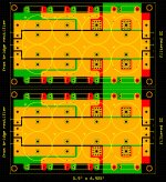
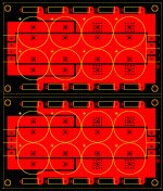
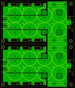
I have designed a new power supply capacitor board for the SIT3X (and other amplifiers). The board is to be fabricated for a stereo pair of channels, but can be cut in half into two separate boards.
The board was lair out using ExpressPCB, but the cost of fabricating it by them would be excessive. I am looking for a volunteer to convert my layout using a design program to can export Gerber files. The layout is shown below, in 3 images:
The board was lair out using ExpressPCB, but the cost of fabricating it by them would be excessive. I am looking for a volunteer to convert my layout using a design program to can export Gerber files. The layout is shown below, in 3 images:
- Both sides
- Top side
- Bottom side
Attachments
I could explore the cost of getting the PCBs made in India, to exact spec. It would be a fraction of the cost.
I could explore the cost of getting the PCBs made in India, to exact spec. It would be a fraction of the cost.
Yes, but they want Gerber files, which I cannot at this time generate.
Fab house can generate Gerber files and submit Layout and Drill details for verification before proceeding to manufacturing.
- Home
- Amplifiers
- Pass Labs
- The SIT-3X Amplifier