Thanks! Amazing parts and circuit design, so I wanted to do my best to pay them their due respect 🙂
Nice build!!!
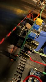
Can you show some more pix of how you have the SIT and PCB mounted? Looks like maybe tall standoffs and the SIT is hiding underneath.
Can you show some more pix of how you have the SIT and PCB mounted? Looks like maybe tall standoffs and the SIT is hiding underneath.
Nice build, May want to increase heat sink size on IRF 510 (Q1)
From experience it runs really hot
From experience it runs really hot
Well done! Congrats on finding the 2SK77B's!!!! I'm still hunting.

Now.... where's that gorgeous pre-amp you're building?

Now.... where's that gorgeous pre-amp you're building?

Leaving for a road trip to Memphis in a few days – thinking seriously about bringing them with me so I can continue listening 🙂
I do have a quick question ZM. When I fired it up (p1 on Mu board set to Max) the Iq was essentially right at 3A2. I could go higher, but not any lower. Common logic suggested I increase R1 (in series with pot) and so I did so. I put 18K at R1, which allows me to lower to around 3A, but not any lower. Is there a limit to what I can do with R1/P1 regarding Iq range?
rail-gate resistor is having some effect, but dominating is voltage across source resistors, feeding Optocoupler
leave it as is, Pa is trusty one, when speaking about sweet spots
if heat is an issue - improvise ....... but stay with Papafigures
you Sissy ........ decreasing Iq ..........

leave it as is, Pa is trusty one, when speaking about sweet spots
if heat is an issue - improvise ....... but stay with Papafigures
you Sissy ........ decreasing Iq ..........
and get rid of that thermal interface between parts and htsnk
no interface + goop help is - logically - better than interface
I know it's hassle to go now inside, dismantling, but better safe than sorry
no interface + goop help is - logically - better than interface
I know it's hassle to go now inside, dismantling, but better safe than sorry
I'll give it a try. Heat is manageable right now, but barely. The top of the device is 8-10C hotter than the hottest spot on heatsink. That seems reasonable to me, but I'm curious what others see.
I went from 3A2 to 3A and didn't see any changes with distortion, so I'll probably stay at 3A for now. I needed to edit the R1 resistor value to be able to get to the 3A
I went from 3A2 to 3A and didn't see any changes with distortion, so I'll probably stay at 3A for now. I needed to edit the R1 resistor value to be able to get to the 3A
Last edited:
make Babysitters
there is no way of managing heat of A Class amp in summer time in other way - at least I'm cringing every time when I think of poor elcos; OCD or not, that's it (ZMOCD, most likely )
in case of using AC, I don't like maintaining winter or Autumn temperature in room, trying to keep minimal difference to outdoor temperature, just to make it bearable ....... which means - even with AC, room temp is higher in Summer
example - crudest Babysitter I made for Papa's Koan - these days heatsinks are substantially colder (than without Bsitter) and top cover is almost cold, comparing to heatsinks
go figure
there is no way of managing heat of A Class amp in summer time in other way - at least I'm cringing every time when I think of poor elcos; OCD or not, that's it (ZMOCD, most likely
)in case of using AC, I don't like maintaining winter or Autumn temperature in room, trying to keep minimal difference to outdoor temperature, just to make it bearable ....... which means - even with AC, room temp is higher in Summer
example - crudest Babysitter I made for Papa's Koan - these days heatsinks are substantially colder (than without Bsitter) and top cover is almost cold, comparing to heatsinks
go figure
- Home
- Amplifiers
- Pass Labs
- The Singing Bush Tips 'n' Tricks