Hi Sy anyone ,
i am still a bit confused about these led's , so i was wonder if any could point me to the right ones.
This is what i have so far could these work
3MM Red LED red light emitting diodes 1000PCS/LOT Free shipping-inDiodes from Electronic Components & Supplies on Aliexpress.com | Alibaba Group
The spec is at the bottom of the page
cheers
skal
The info you need (Vf vs current) isn't there. Probably OK, but you never know until you have them in hand and can measure Vf and impedance.
cool , . Just got some leds and want to set up a test rig to measure things .
What am i suppose to be measuring ?
i got some 12at7, pcc85 and 5687
cheers
What am i suppose to be measuring ?
i got some 12at7, pcc85 and 5687
cheers
Ok ,just built the screen reg circuit from sy web page ,and i can only adj 20v or so this is without a load.
Are these voltages with in spec or is there something wrong..
max voltage out 290vdc
min voltage out 269vdc
here are my Tip50 and Lm317 voltages
b 349vdc
e 293vdc
c 293vdc
voltage at lm317 100k short to grn
in 294vdc
out 282vdc
ajt 281 vdc
voltage at lm317 100k open to grn
in 301vdc
out 290vdc
ajt 287 vdc
cheers
Ok ,just built the screen reg circuit from sy web page ,and i can only adj 20v or so this is without a load.
Ar
I didn't check your voltages, so can't say if everything is ok, but that sounds about right.
It doesn't have a big range of adjustment, because most of the current is going through the 56k resistor.. The potentiometer is just for fine tuning.
edited to add:
I almost never get proper regulation when using a 200ohm resistor where it is in the schematic.. Maybe due to the brand lm317's ive got or something.. not sure.. I try to use 120ohm. but then you need to recalculate all the voltage setting resistors.
Last edited:
cool , . Just got some leds and want to set up a test rig to measure things .
What am i suppose to be measuring ?
The Red Light District, p2 Top part of the page.
I almost never get proper regulation when using a 200ohm resistor where it is in the schematic.. Maybe due to the brand lm317's ive got or something.. not sure.. I try to use 120ohm. but then you need to recalculate all the voltage setting resistors.
I've run into the same issue with some lots, the datasheet specs notwithstanding. I *suspect* that these are counterfeit 317s, but with 120R, they work fine.
I almost never get proper regulation when using a 200ohm resistor where it is in the schematic.. Maybe due to the brand lm317's ive got or something.. not sure.. I try to use 120ohm. but then you need to recalculate all the voltage setting resistors.
Don't forget that the current flowing from the ADJ pin through the 56K resistor is going to impress itself on the output. You'll pick up 3 to 5V from the 50 to 100uA of Iadj x 56k
I've been use Panasonic 3W -- 36K + 20K 3W.
A nice 4.7uF/400V polypro from ADJ to GND will knock down the LM317's noise quite a bit.
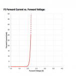
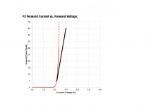
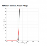
Is it possible to estimate the dynamic impedance of a led by looking at the current/voltage chart in the datasheet?
I found a round 5mm led with a rather good looking graph: WURTH ELEKTRONIK 151051RS11000
http://katalog.we-online.de/led/datasheet/151051RS11000.pdf
The forward voltage of this led is 2,1V. I was thinking that 3 chains of 5 leds could work; 10,5-10,75 volts and ~25-27mA per chain.
I found a round 5mm led with a rather good looking graph: WURTH ELEKTRONIK 151051RS11000
http://katalog.we-online.de/led/datasheet/151051RS11000.pdf
The forward voltage of this led is 2,1V. I was thinking that 3 chains of 5 leds could work; 10,5-10,75 volts and ~25-27mA per chain.
Attachments
Is it possible to estimate the dynamic impedance of a led by looking at the current/voltage chart in the datasheet?
Sure, it's dV/dI (i.e., the slope of the tangent line) at whatever current you'll be operating the LED. That one looks like roughly 12R at 5mA operating point.
Attachments
That's running them uncomfortably close to their limits. You might get away with it, but I wouldn't guarantee it.
I have asked earlier about making the preamp voltage lower and use the same transformer for both stages. This was in 2009, so you may not remember. 😀
You said it will not work well. Not enough swing, not enough drive, more distortion.
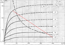
Now after browsing trough more of this thread I have found out that it's possible to run the EL84 plates up to >400 volts as long as the screen is below 300 and dissipation within limits. Now with a 400 volt B+ it could work to run both stages from the same transformer. Right?
I realize that a higher B+ will make the screen supply dissipate more and the voltage rating of the transistor may not be enough. Anything else to think about?
I usually build my projects in too small enclosures so it will be difficult to add another transformer later. 🙂
You said it will not work well. Not enough swing, not enough drive, more distortion.
Now after browsing trough more of this thread I have found out that it's possible to run the EL84 plates up to >400 volts as long as the screen is below 300 and dissipation within limits. Now with a 400 volt B+ it could work to run both stages from the same transformer. Right?
I realize that a higher B+ will make the screen supply dissipate more and the voltage rating of the transistor may not be enough. Anything else to think about?
I usually build my projects in too small enclosures so it will be difficult to add another transformer later. 🙂
That's running them uncomfortably close to their limits. You might get away with it, but I wouldn't guarantee it.
Many thanks for the responses! I think I'm beginning to understand more of this now. This is a learning process for me. When the amp is overdriven a lot and the waveform approaches a squarewave the tubes will take turns pulling about 130mA. The Wurth leds I was looking at are rated for 30mA continuous so 3 chains of leds can indeed bee too little. At least 5 chains would be better.
Also I have been looking at the EL84 datasheets and drawing loadlines. If I have 400V B+ it seems like the output transformer needs to be 10-12k. In the picture below I have plotted a 3k loadline (=12k transformer). Most of the load line is above maximum dissipation but the operating point is at only 20mA so I guess it should be fine...
Attachments
- Home
- Amplifiers
- Tubes / Valves
- The Red Light District - another PP EL84 amp