I have not started my project yet. Still thinking and trying to figure out how things work.
What have I learned today? When an amplifier operates in push pull class AB, the tubes are loaded differently in the A part and the B part. In class A each tube sees 1/2 of the OT:s primary impedance. In class B, only one tube conducts at a time, so only half of the primary windings are in use. The impedance is now 1/4 of the OT primary impedance.
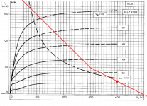
To get a better understanding of what is happening I have now plotted a combined loadline (attached below).
400V B+
8k output transformer (2k and 4k slopes)
250V Vg2
25mA Ia per EL84
I don't know if this is the correct way to locate the transition from A to B, but I have assumed the following: When the signal voltage at Vg goes down enough the tube stops conducting. At this point Va=500V. At the same time the Va of the other tube should have come down by the same amount to Va=300V (assuming symmetry). The anode can swing between 300-500V in class A, the rest is class B. The maximum power should be about 2,5W in class A and 19,5W total.
Also when looking at these lines the limits for anode voltage starts to make sense to me. The 300V limit in the datasheet is most likely valid for class A operation. To maximize class A power, the tube needs to be loaded with a higher impedance to get more voltage swing. In pure class A the anode can swing up to almost double the operating point, so the idle voltage needs to be kept lower. In pure class B the Va never goes above the idle voltage and class AB is something in between. In my graph Va goes up to max 500V. The Mullard EL84 datasheet says Va max=300V and Va(b) max=550V. I'm guessing (b) stands for class B (?). The same datasheet also says Vg2(b) max=550V.
It would be exciting to see how much more you can safely get out of a pair of EL84:s. Posters on this forum have reported that the EL84 can’t tolerate Vg2>300V. But maybe it’s mostly about how the tube is loaded. Personally I would be looking at the point where the load line crosses Vg=0 (saturation point). When the amplifier is overdriven the waveform is chopped off. The more overdrive, the more time the tubes will spend at saturation. In my plot the saturation point is Ia=135mA and Ua=112V. Dissipation is 15,1W but even at extreme overdrive each tube conducts only half of the time so I’m guessing this is still safe (15,1/2=7,55W) as long as the leds can handle continuous 135mA. With a higher B+ a slightly higher impedance output transformer would be needed to keep the saturation point well below 2*Pa max.
What more have I learned? I found a led for a "White Light District": The Cree MC-E RGBW is a 7x7,5mm unit consists of of two white, one red and one green led.
The datasheet shows that the the different leds have different forward voltage and impedances. The impedance of the white and red ones look very good at ~50mA and as the green one is not terrible I estimate a total serial impedance of 9 ohms and a forward voltage ~10,05V. There is also a version with four white leds with less impedance and about 11V forward voltage. These units can be bought premounted on a round heatsink for easy installation. This led can handle up to 700mA.
What have I learned today? When an amplifier operates in push pull class AB, the tubes are loaded differently in the A part and the B part. In class A each tube sees 1/2 of the OT:s primary impedance. In class B, only one tube conducts at a time, so only half of the primary windings are in use. The impedance is now 1/4 of the OT primary impedance.
To get a better understanding of what is happening I have now plotted a combined loadline (attached below).
400V B+
8k output transformer (2k and 4k slopes)
250V Vg2
25mA Ia per EL84
I don't know if this is the correct way to locate the transition from A to B, but I have assumed the following: When the signal voltage at Vg goes down enough the tube stops conducting. At this point Va=500V. At the same time the Va of the other tube should have come down by the same amount to Va=300V (assuming symmetry). The anode can swing between 300-500V in class A, the rest is class B. The maximum power should be about 2,5W in class A and 19,5W total.
Also when looking at these lines the limits for anode voltage starts to make sense to me. The 300V limit in the datasheet is most likely valid for class A operation. To maximize class A power, the tube needs to be loaded with a higher impedance to get more voltage swing. In pure class A the anode can swing up to almost double the operating point, so the idle voltage needs to be kept lower. In pure class B the Va never goes above the idle voltage and class AB is something in between. In my graph Va goes up to max 500V. The Mullard EL84 datasheet says Va max=300V and Va(b) max=550V. I'm guessing (b) stands for class B (?). The same datasheet also says Vg2(b) max=550V.
It would be exciting to see how much more you can safely get out of a pair of EL84:s. Posters on this forum have reported that the EL84 can’t tolerate Vg2>300V. But maybe it’s mostly about how the tube is loaded. Personally I would be looking at the point where the load line crosses Vg=0 (saturation point). When the amplifier is overdriven the waveform is chopped off. The more overdrive, the more time the tubes will spend at saturation. In my plot the saturation point is Ia=135mA and Ua=112V. Dissipation is 15,1W but even at extreme overdrive each tube conducts only half of the time so I’m guessing this is still safe (15,1/2=7,55W) as long as the leds can handle continuous 135mA. With a higher B+ a slightly higher impedance output transformer would be needed to keep the saturation point well below 2*Pa max.
What more have I learned? I found a led for a "White Light District": The Cree MC-E RGBW is a 7x7,5mm unit consists of of two white, one red and one green led.
An externally hosted image should be here but it was not working when we last tested it.
The datasheet shows that the the different leds have different forward voltage and impedances. The impedance of the white and red ones look very good at ~50mA and as the green one is not terrible I estimate a total serial impedance of 9 ohms and a forward voltage ~10,05V. There is also a version with four white leds with less impedance and about 11V forward voltage. These units can be bought premounted on a round heatsink for easy installation. This led can handle up to 700mA.
Attachments
Last edited:
Keep in mind that you're building an amp to drive a loudspeaker. The impedance won't be constant and it won't be resistive. Sweating the loadlines too much won't really help you- they're a rough guide at best. In real life, they will be ellipses and vary with frequency. With that in mind, I raised the B+, lowered the idle current to keep within power ratings, verified that I hadn't compromised the distortion, checked the power output, then put the amp back in my system. Very scientific. 😀
Hi Sy,
my 600-hlmp leds have landed, these things are small 😱, i have a couple of questions about the building of the led array.
1} is it 6 or 7 led's per string
2} where do i put the 4.7 ohm resistors in each string , do i put them in the cathode end
3} how many string in parallel
cheers
skal1
my 600-hlmp leds have landed, these things are small 😱, i have a couple of questions about the building of the led array.
1} is it 6 or 7 led's per string
2} where do i put the 4.7 ohm resistors in each string , do i put them in the cathode end
3} how many string in parallel
cheers
skal1
Yes, they ARE tiny! 😀
1) It depends on your EL84s. There's a lot of manufacturer to manufacturer variation. I'd start with 7, and if you can't get the idle current high enough, short one out per string.
2) Since they're in series, it doesn't matter. Whatever is convenient.
3) I used seven strings, but it's not terribly critical.
Good luck and tell me how it goes.
SY are you ever going to create a PCB for this project? I know I would be interested in one.
How is progress going on the RLD's big brother?
How is progress going on the RLD's big brother?
I am brain-challenged for PCB design, so that will have to be someone else. I think Jack Walton did a design a few years back, but it was too expensive because of the size.
The bigger version keeps getting pushed back in my queue. I wish I had more lab time...
The bigger version keeps getting pushed back in my queue. I wish I had more lab time...
Sy, do you know if anyone designed a board for just the LED array?I am brain-challenged for PCB design, so that will have to be someone else. I think Jack Walton did a design a few years back, but it was too expensive because of the size.
Pinkmouse did some years back, but he doesn't have the files any more. It looks pretty easy, and if anyone wants to do it and make the files publicly available, you have my blessing.
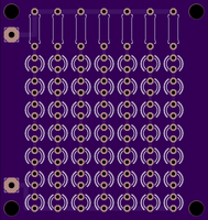
Go to https://oshpark.com/shared_projects/rkU0U4LT pay them $17 and in about 3 weeks you'll get 3 of these at your door. This is untested, but it is hard to imagine what could go wrong.
Hi Sy,
I am having at bit of bother with the screen voltage reg , for some reason ,it keeps blowing the 20v diode , need some help please .
cheer
skal
I am having at bit of bother with the screen voltage reg , for some reason ,it keeps blowing the 20v diode , need some help please .
cheer
skal
The 10K'S measure fine out of circuit , but measure 2.5k in circuit , is this due to some parallel connection with the tip50 and the 100 ohm resistor ?
yeah tip 50 checks out ok , diode in the right way black strip facing base of tip 50.
I have a couple tip 50's left and a couple diode and lm317 so i will try again .
cheers
I have a couple tip 50's left and a couple diode and lm317 so i will try again .
cheers
cool i will back as soon as possible , should there be a difference of 12v from base of tip 50 to anode of diode ?
Yes, the diode is supposed to hold that base voltage 12V above the output of the regulator (to which the Zener's anode is connected).
- Home
- Amplifiers
- Tubes / Valves
- The Red Light District - another PP EL84 amp