
You should listen first, even with lab supply. 🙂
Patrick
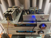
I get something better than lab supply 😀
Everything works beautifully... really a piece of art!
I started to listen and the HD800 simply disappear... awesome! I can't imagine what will be the DAO!
Thanks Patrick to share with us your refined knowledge and... for your patience 🙂
Regards,
Enrico
Attachments
I‘m just about to finish the SLHPA from the 2nd GB. Can anybody please point me to a wiring diagram for the SMD Danyuk Cross Feed PCB V2. 
I‘m just about to finish the SLHPA from the 2nd GB. Can anybody please point me to a wiring diagram for the SMD Danyuk Cross Feed PCB V2. View attachment 818031
No diagram needed friend,
RCA input R/L to Ri / Li & Gnd, then take the outputs (middle pins) from under the pot/board pins to the amp inputs.
Just rebuilding mine using the integrated motherboard Xfeed, hopefully done very soon!
Transistor matching took a while but the overlap between P and N types was okay. I found enough matches. Hfe is >550.

Ordering parts...
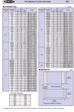
I can see Beyschlag resistors have specified type which allows me to check the wattage.
For example I expected R19,20 to be more beefy. And indeed, Beyschlag is 0.4W.
As for the other Susumu 0805 resitors is it ok to order 0.1W or shall I go for 0.25W?
As for active parts are alternatives worse or just not used/tested in this circuit?
Yes, in the SMT world metal film is called "thin film" and metal oxide is called "thick film".
Thin film are best whereever low distortion matters, such as feedback networks, active filters.
For SMT caps you won't find PP (polypropylene) as it melts well before solder does, but PPS types (polyphenylene sulfide) are a great low-distortion substitute.
Thin film are best whereever low distortion matters, such as feedback networks, active filters.
For SMT caps you won't find PP (polypropylene) as it melts well before solder does, but PPS types (polyphenylene sulfide) are a great low-distortion substitute.
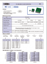
These are some variation on acrylics I think, high energy density, good temperature resistance, not as good performance as PP or PPS I believe, all the Rubycon literature compares them favorably to X7R MLCC, and I think they are a good all-rounder, likely to surplant mylar and even MLCC in the long term.
Ordered 2 batches of parts. I have already one batch (including pnp transistors) at home.
The other packet (with npn's) has arrived at my office. However, given the virus situation, we have implemented working from home shifts. I am on my at home shift so matching is kind of difficult at the moment...
The other packet (with npn's) has arrived at my office. However, given the virus situation, we have implemented working from home shifts. I am on my at home shift so matching is kind of difficult at the moment...
So I skimped a bit in the output transistor department and ordered twenty of each of the Sanken.
First run for finding P-N pairs was with the good old DCA75.
Here the range went from an hFE of 140 to 200 with the P-type and 110 to 178 with the N-type.
But then I thought a measurement at the approximate conditions of the SL HPA would be better than the 5mA Ic at room temperature.
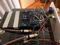
Rod Elliott’s esp Project 106 came to the rescue. I built a scaled down version for only 150mA with parts at hand. Well two actually, P and N tester.
Then I thought about temperature control and set up an IRF044N on an old Dell CPU cooler with a temperature controlled fan. So while pumping about 40W of heat into the cooler, the fan levels the temperature on a nice steady value that can be monitored via the supply voltage of the fan.
IB is measured with an old HP972A that was due to calibration in 2017 but I trust this one🙂
With this hFE measurement (aka IBhFE🙂, compared to the one from DCA75, I found the hFE higher in general and with a relative constant rising delta for higher values. The delta of the N group is smaller than that of the P group.
So that made it harder to find two lousy pairs …
The IBhFE measurement came out at a range of 165 to 232 for PNP and 121 to 197 for NPN. Only two pairs with a slight disbalance towards N-type devices were found.
PN
165 / 168
167 / 170

View attachment 1
View attachment 1
View attachment 1
View attachment 1
First run for finding P-N pairs was with the good old DCA75.
Here the range went from an hFE of 140 to 200 with the P-type and 110 to 178 with the N-type.
But then I thought a measurement at the approximate conditions of the SL HPA would be better than the 5mA Ic at room temperature.
Rod Elliott’s esp Project 106 came to the rescue. I built a scaled down version for only 150mA with parts at hand. Well two actually, P and N tester.
Then I thought about temperature control and set up an IRF044N on an old Dell CPU cooler with a temperature controlled fan. So while pumping about 40W of heat into the cooler, the fan levels the temperature on a nice steady value that can be monitored via the supply voltage of the fan.
IB is measured with an old HP972A that was due to calibration in 2017 but I trust this one🙂
With this hFE measurement (aka IBhFE🙂, compared to the one from DCA75, I found the hFE higher in general and with a relative constant rising delta for higher values. The delta of the N group is smaller than that of the P group.
So that made it harder to find two lousy pairs …
The IBhFE measurement came out at a range of 165 to 232 for PNP and 121 to 197 for NPN. Only two pairs with a slight disbalance towards N-type devices were found.
PN
165 / 168
167 / 170
View attachment 1
View attachment 1
View attachment 1
View attachment 1
- Home
- Amplifiers
- Headphone Systems
- The Pioneer Super Linear Circuit