😉
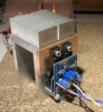
How did you attach the heatsink to the U-channel ?
Aluminium solder ?
Great matching, by the way.
Patrick
How did you attach the heatsink to the U-channel ?
Aluminium solder ?
Great matching, by the way.
Patrick
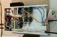
Thanks🙂 That was the most time consuming part of the build. But it is definitely worth the effort.
The little CPU heat sink is attached with just one screw and some Arctic MX-4 thermal compound. The copper bars are glued to the U with arctic 2k thermal glue.
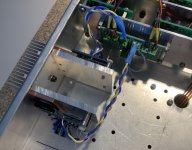
But at this point the sink is just experimental. I wanted to check the temperature @ 150mA bias and maybe it will be enough to bolt the assembly to the aluminium lid of the final amp.
They won't get warm even with a normal size aluminium case large enough for a desktop headphone amp.
But low working temperature not only means long life, but also minimum DC offset and bias drift.
Which is why I normally use heatsinks.
And it allows me to wind up the bias if I want.
(not that it is necessary)
Patrick
But low working temperature not only means long life, but also minimum DC offset and bias drift.
Which is why I normally use heatsinks.
And it allows me to wind up the bias if I want.
(not that it is necessary)
Patrick
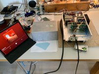
So the SHPP is ready and I have first music [emoji106]
I tweaked the SHPP a little towards higher sensitivity.
R2,4 is 90k in this one and the trigger point is 55mV as predicted. I also used the reset function.
Big thank you to all the people involved in this project here on diyaudio [emoji120]
I have to say that none of the other HPAs sounded so right from the first moments.

Hi, do you already show a balanced slc ?
Thanks
Best regards
Sebastien
Hi, no. This is the original circuit. But the enclosure it is sitting in also has one path for symmetrical connections. The SLHPA only uses only one single ended half of each channel. At the moment I’m working out if I want the SLHPA only for the headphone output or if I provide also a line level output from it. Maybe try something like 50 Ohm in series.
Patrick, persuaded by your thread i breadboarded the sister circuit from this site.
the Headphone amplifier
And it works well while really does sounding something special. But i cant seen to adjust the gain by changing the 10k and the 1k resistors that are tied to the ground, which i believe are r15 r7 in your circuit?
Right now i have them both at 10k and the gain is too high.
Id like to bring down the amp to the lowest gain possible. Even unity gain is ok. Please help!
I did, Patrick. I cant find any reference to setting the gain for the darlington version except that it is easier on the diamond version. 🙁
Hi Patrick, first of all, thanks for this awesome design. I have a question, I have a pair of 2SK389, idss is 17.6mA-17.7mA, 17.7-17.7mA. Is it any good for input buffer?
- Home
- Amplifiers
- Headphone Systems
- The Pioneer Super Linear Circuit

