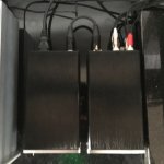
If I wanted to be cheap and lazy about the power supply, would something like this work well enough?
No. Well, not directly. You will need an additional circuit to make a virtual ground, as the power supply doesn't provide a common reference.
I ran across a build where someone combined the switch board with the Emerald. The interesting thing was the switch board was mounted on the outside of the enclosure. Does anyone have a picture or additional information on that build?
I don't remember seeing that. If you want to access the Switchboard DIP switches without opening the case, you can make a small cutout and mount the switchboard flipped over so the switches are facing the case. Or you can keep the board as is but mount the switches on the underside of the board.
I don't remember seeing that. If you want to access the Switchboard DIP switches without opening the case, you can make a small cutout and mount the switchboard flipped over so the switches are facing the case. Or you can keep the board as is but mount the switches on the underside of the board.
All good ideas. I could also use some tall standoffs and raise them up to a cut-out in the top of the case too.
Or mount everything on the top, which is what I do. (technically it's the bottom of the Hammond 1590 case, but the case is flipped upside down in use)
Hello Again!
My next build - phonoclone - again with the HUM issue.
Again anodized chassis - but i filed it in the areas where it connects and multimeter beeps happily on various parts of the enclosure.
PSU
The transformer and earth in IEC is connected to the chassis.
PRE
Ground connected to the lug. RCA isolated from chassis ( checked that before soldering wires)
So it HUMs - but what worries me is that grounding TT to the post makes no difference. Like there is no reaction. I know that TT works well, tested with 3 other preamps.
What else i might have missed ?
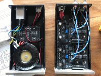

Everything looks in good order, I'm fairly confident there are no mistakes, but just to confirm please run through the per supply voltages for me, V++ V+ etc.
The most most likely scenario is you have set the gain too high for the cartridge. I.e R2 is too high.
The most most likely scenario is you have set the gain too high for the cartridge. I.e R2 is too high.
V++ and V-- are 16.3v on load, without load ( pre disconected) its 10.8.
Ref points ( after trimming with pots) 13.3 on one board, 12.5 on second.
Cart I'm running is DL-103, R2 i took from the BOM - 150R
Now i read BOM file and i see i should buy the 681R for DL103 - will do,
one more quesiton though - in future i plan to use it with DL103R - what value for R2 should i have than?.
Thanks as always Richard 🙂
Last edited:
Changing R2 from 150R to 681R would be expected to make the problem worse not better, as the gain will increase.
I've had a chance to listen to the hum in your Youtube vid. It's definitely a sharp buzzing sound - unusually nasty - i.e. rectified 120 Hz diode sawtooth wave rather than transformer or AC pickup or just white noise. That suggests the source is internal to the phonoclone power supply rather than interference at the TT end. It's also quite loud considering the configured gain of the phonoclone is not so great.
I have two suggestions:
1. replace the DL103 cart and phono cable with a 40 ohm (approx) resistor soldered between the tip and ring of the input RCA jacks. This dummy load will simulate the cartridge without risk of damage and allows the influence of the TT to be completely removed from the equation.
2. if you don't have a scope, measure the AC voltage on V++, V-- and V+, V-. On the V++ and V-- it should be less than 1 VAC. On the V++ and V-- it should be zero, measuring a couple of mV at most. My concern here stems from the fact that you only have 16 V on V++ and over 13 V on V+. That's not a huge amount of overhead and perhaps the S-Reg output has dropped out of regulation, or there is some other issue meaning it is nor filtering out the ripple voltage properly.
Ok, I will do all the measurements as you instructed, I also just bought an old scope - I'll try to learn how to use it over the weekend, if this will be a filtration issue - what is the potential fix? bigger caps?
My multimeter is too shitty to catch such small AC values ( only two scales 750/200) i fired up the the scope for the first time and i picked up something saw alike ( on the picture ) before filtration V++ V--, tried more sensitive on V+ and V- and on 50mv setting there is very very tiny "floatation" of the curve,
didn't test yet soldering the resistor - i only found 100R - will it be fine?
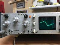
didn't test yet soldering the resistor - i only found 100R - will it be fine?

You can connect two 100 ohm resistors in parallel to make 50 ohms.
Your 'scope has 10 mV/div gain range, that's sufficient for our purpose here.
Of course the V++ V-- will have a large sawtooth wave pattern. Those get removed by the S-reg, and if you do not observe a similar pattern on V+ then all is good in the power supply. Next is to measure the phonoclone output with the scope to see if the same sawtooth wave is present, or what shape and magnitude the noise signal has. The shape can tell you a lot about what the source is.
Remember you have to have an input load (the cartridge or dummy resistor) connected to force the input stage into amplifying the noise signal. Open circuit the gain is only 30 dB so the output noise is very low.
Since the V+ is OK, we start to think back instead about interference and noise pickup. Again though, nothing about your build suggests any potential issues. It all looks well done.
I soldered in 50R resistors- as a result a dead silent preamp. Just some tiny hiss/noise on full volume so all good. So something is indeed wrong with my TT - new chase begins.
I just tested it with another preamp with a SUT - as well i can hear the same noise just quiter ( didnt notice it before) so something just recently went wrong with the TT.
Thank you Richard for help.
One last question is what R2 value should i use for DL-103R?
I just tested it with another preamp with a SUT - as well i can hear the same noise just quiter ( didnt notice it before) so something just recently went wrong with the TT.
Thank you Richard for help.
One last question is what R2 value should i use for DL-103R?
Last edited:
R2 should be about 680 ohms, though the exact value is not critical.
It sort of sounds like the ground connection internal to the TT has gone open circuit somewhere, so parts that were supposed to be connected to the ground wire are left floating. That or there is some weird noise pickup into the cartridge or phono cables for example, like a nearby wifi or switching power supply. If its possible to change to a different set of phono interconnects I'd give that a shot at least.
It sort of sounds like the ground connection internal to the TT has gone open circuit somewhere, so parts that were supposed to be connected to the ground wire are left floating. That or there is some weird noise pickup into the cartridge or phono cables for example, like a nearby wifi or switching power supply. If its possible to change to a different set of phono interconnects I'd give that a shot at least.
My TT is Linn Basik - where cable connects only to the tonearm (via 5din 90 degree socket) - there is no grounding connection to the motor - both are seperatly connected to MDF chassis. Most likely cable has gone bad - couple of years ago i already had this problem - replacing the cable helped
it WORKS now great. Wierdest thing ever, i removed the cart and mounted it back- no hum. i suspect that cables in headshel are no good anymore.
Preamplifier works great now- but some more gain will be appreciated so I ordered a pair of dale's 681.
Sounds beautiful! Thank you Richard, wonderful preamp!
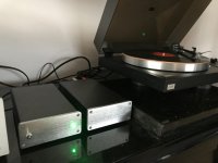
Preamplifier works great now- but some more gain will be appreciated so I ordered a pair of dale's 681.
Sounds beautiful! Thank you Richard, wonderful preamp!


Last edited:
Hi RJM
I want to test the 4.4 point to point wired.
Is it 2x3 decoupling caps per IC?
Looks like, if i preview the PCB.
Normal i would have done it with to i parallel, eg 100uf+.1uf.
Br Morten
I want to test the 4.4 point to point wired.
Is it 2x3 decoupling caps per IC?
Looks like, if i preview the PCB.
Normal i would have done it with to i parallel, eg 100uf+.1uf.
Br Morten
- Home
- Source & Line
- Analogue Source
- The Phonoclone and VSPS PCB Help Desk