Sounds to me like you might have more than one problem. At the bottom of post #1 of this thread is a link which should take you to post #3775 in this thread.
Work your way through that and see where it falls down. If you suspect a problem with the rail switching (FET's and control circuit) then the FET's can be linked across from drain to source for testing. That will permanently pass the rail voltage to the audio circuitry.
Thanks for the prompt response. Yes I have gone through all the troubleshooting steps which I have found relevant on this forum via search including #3775. All stages passed except the -ve rail and NMOS part, only when the problem surfaces. After a long cooldown and I start the amp from cold, there were times long enough for me to perform measurements and ALL the steps passed exactly as stated in nwavguy's website! This is exactly why I am at wits end, trying my luck on this forum and see if anyone has seen the same odd issue.
The closest I can find here (which share the exact symptoms) is this post here starting #4702. Though it seems like his was due to just a broken trace, which is not in my case unfortunately (or fortunately?) 🙁 Confirmed this when the -ve rail was acting up by measuring individually each ends of the leads of R8, Q2, C21, R25, R6 and U2 pin 7 which is on the same node as the gate. Do you reckon that it's a problem with the 2903 instead?
The clues are always in careful voltage measurement.
If you have followed post #3775 then you should be seeing -12 volts (or -8 or so if on battery) applied to pin 4 of U2 and also the FET Q2. Those voltages should be a constant and ever present.
For Q2 to turn on and pass the voltage to the rest of the amp we need for the comparator (the 2903) to go high on pin 7. That means pin 7 should be approximately the same voltage as pin 8 (12v on mains, 8v or so on battery).
So those are the first things to check. Measure on the pins of the FET (be careful not to short the pins) to confirm the voltages are present.
Hello world,
I have successfully built the O2HPA from the documents and gerber files provided by nwavguy (thanks a lot for that!).
Dear DIY’rs can some share the gerber files with me pleasr....quite interested to build O2 for long time...
Dear DIY’rs can some share the gerber files with me pleasr....quite interested to build O2 for long time...
Available on the nwavguy blog google drive
NwAvGuy: O2 Details
I had some made by pcbway a couple of months ago (their basic specs 1oz Cu, us$5 for 10 boards (for me delivery was another $10)). They did a fine job and I got one more than I paid for.
I used the BOM from here to get more recent/upgrade parts
Last edited:
Hey guys, am new to DIY audio here (but I do have DIY experience in other areas) and I want to build the upgraded version of the O2 amp listed here O2 upgrades
I'm also using the custom O2 mod guide on JDS labs to add RCA inputs and a 1/4 inch jack.
However, I have run into a couple of problems:
- I am unable to find the LED listed in the original BOM in small quantities. Most places have a minimum order way more than what I need. Can this LED be replaced with any 3mm red LED, or does it have to be specifically that? I read that he chose that LED so that it isn't too blinding and as someone who has used LEDs in other DIY projects, I completely understand how bright they can get! If I were to pick a 3mm red LED at 80mcd, that should work without issues right?
- For the 1/4 output jack, this is the one that JDS lists on their website JDS Labs - Neutrik 1/4in Stereo Jack
Does anyone know a mouser part number for this jack, or will any similar stereo 1/4inch female jack work?
- Lastly, enclosures! Does anyone know of any alternative to the common B2 box enclosure? Also, where do you guys get your front and rear plates from? I can order them off JDS labs but the shipping costs are a real killer. Shipping costs to where I'm at is around 2/3 of the price of the items already. This means that the price of getting the enclosure makes up half the cost of the entire project.
- Is it possible to use the amp without a (proper) case? I understand that there might be interference issues from an open design (I got the bravo v2) but I am willing to do a build first and source/save up for a case later.
Thanks all 🙂
The clues are always in careful voltage measurement.
If you have followed post #3775 then you should be seeing -12 volts (or -8 or so if on battery) applied to pin 4 of U2 and also the FET Q2. Those voltages should be a constant and ever present.
For Q2 to turn on and pass the voltage to the rest of the amp we need for the comparator (the 2903) to go high on pin 7. That means pin 7 should be approximately the same voltage as pin 8 (12v on mains, 8v or so on battery).
So those are the first things to check. Measure on the pins of the FET (be careful not to short the pins) to confirm the voltages are present.
Yes Mooly, everything was working perfectly fine, exactly as you expected, as described in nwavguy's original article as well as those set out in your guide to troubleshoot, until some random time it just self-triggers and fails.
So I thought about the previous person's case and reheated all the solder joints at the IC socket of 2903, now it has been working for 3 days without any issues. I am very certain I have visually inspected all solder joints to be nicely shaped and stuck onto both the PCB and the leads. I have even individually measured connection between solder and the leads and found that they have almost 0 ohms of resistance. I am completely dumbfounded by this mystery.
Not taking any chances, using another sacrificial IEM to continuously test it under all sorts of conditions I would use the amp in, hopefully nothing unexpected happens!
Cheers for your help! 🙂
You have to do the checks during the time its not working. That essentially means recording six things.
1/ The positive unswitched voltage to FET Q1
2/ The negative unswitched voltage to FET Q2
3/ The positive switched output from the FET Q1
4/ The negative switched output from the FET Q2
5/ The output of comparator U2a
6/ The output of comparator U2b
Measure and record these voltages in the faulty state and see what you get.
Attachments
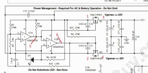
I currently can not source the P-channel fqu11p06, can it be substitute by something like 2SJ406?
Last edited:
The quick answer is no. This is because the comparator swings the gate to negative -12 volts and so with the source at +12 volts you are exceeding the FET's -/+ 20 volt Vgs limit.
[...]
- I am unable to find the LED listed in the original BOM in small quantities. Most places have a minimum order way more than what I need. Can this LED be replaced with any 3mm red LED, or does it have to be specifically that? I read that he chose that LED so that it isn't too blinding and as someone who has used LEDs in other DIY projects, I completely understand how bright they can get! If I were to pick a 3mm red LED at 80mcd, that should work without issues right?
[...]
As Mooly said: "Replacing R9 with a 47k multiturn preset allows different LED's to used and the trip point to be adjusted accurately by monitoring the combined battery voltage and setting the preset to cut off when the combined battery voltage falls to say to 14 volts (two 8.2 volt batteries containing 7 cells each and discharging to 1 volt per cell)".
Also, http://uk.farnell.com/w/c/optoelect...v|2.1v|2v&sort=P_ATT_BASE_VALUE_1000024_EN_GB might help perhaps.
The quick answer is no. This is because the comparator swings the gate to negative -12 volts and so with the source at +12 volts you are exceeding the FET's -/+ 20 volt Vgs limit.
Thanks, is there a way to bypass the power management circuit?
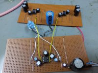
Hi y'all.
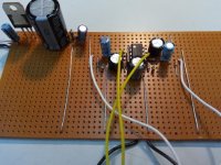
I'm currently building single supply O2 on proto board (not PCB), the op amp currently just running from 12V DC from my LM317. Which it get it's supply from a noisy 15V SMPS.
Currently only completed the gain stage, using NE5532 with a gain of 2 (inverting topology). Currently my noise is around 5uV. Next step is to wire up the NJM4556, which have to add big value cap at the output.
Eventually I will build a PCB and power by a single 9V battery.
Attachments
Last edited:
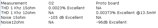
Single supply amps are a valid option and 9 volts is sufficient for most low impedance high efficiency headphones.
I intend to use it to drive my in-ear earphone during my daily commute. Earphone is a dual driver config which reduce impedance down to 8 ohm. Very likely affect the bass region of my phone's 3.5mm output.
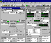
Run a quick few measurement, I use 12 ohm instead of 15 ohm done in the original measurement. I also direct solder resistor which given me 80+dB crosstalk which will degrade once use a 3.5mm jack.
Attachments
Last edited:
 looks good.
Any chance I can use a small AC transformer with 15V 500mA rated secondaries as a power supply...I suspect it can.... unless anyone can guide me for AC-AC transformer circuit..
- Home
- Amplifiers
- Headphone Systems
- The Objective2 (O2) Headphone Amp DIY Project